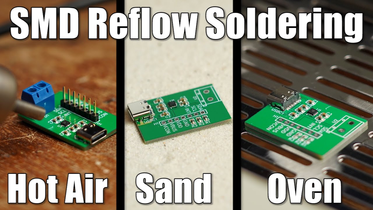
How to do SMD Reflow Soldering properly! Hot Air VS Sand VS Reflow Oven
video description
Date: 2020-09-05
Related videos


Comments and reviews: 9
--
Maybe with some better design of the solder mask and pcb layout around the IC and USB-C connector it would have been even easyer to solder. Why did you not reduce the solder mask openings at the USB-C connectors pads, so you would get a line of solder mask between the pads? Usually you can go down to 0. 05mm solder mask expansion on the pads and 0. 07mm minimal solder mask width. And you never ever bridge pads in cooper directly under the IC like you did on the MLP package, at least not in any professional PCB design. I know it's tempting and looks simple in the layout software, but it makes board production and inspection a lot harder and does not offer any electrical or space saving benefit in this design.
And then you put that waay too big blob of solder at the first hand soldered terminal. Aaarrgh!
reply
Niklas
I think you were using too much soldering paste for the board. Having a stencil is great but for my homebrew projects I was always put off by the additional costs: D
As for my experience, putting on the soldering paste using a syringe with a very fine end cap (around 0, 5 mm) makes the dosing on every pad quite easy.
Afterwards you will need to develop a little feeling with the hot air gun but once you find it, it produces very good soldering bonds.
I never had the problem of molten ics or something like that.
Keep up the good work! Very good content!
reply
Airzone
In my own experiences: 1) Hot air is easily prone to overheat electronics, and if you're too quick, to create cold joins. A USB connector is an inconvenient loss, but an atmega dying after a few hours is a bit more of a headache. 2) No experience - my wife would kill me if I had sand on the stove. lol. 3) That oven benefits from propping your PCB up on some PCB scrap. Ideally on the edges / corners to minimise anything underneath it. The tray will wick away the heat built up in your PCB and cause the normal profiles to fail.
reply
Calvin
usually, when I'm doing SMD, I use a hot air gun almost exclusively. I typically use MG Chemicals flux and a 60/40 solder blend. I usually tin the pads with as much solder as they can hold with my trusty TS-100, and the components as well (if they are large enough. and usually, the flux lets the solder flow enough that the connections are solid. It does require a little extra cleanup with 70% isopropyl alcohol and a toothbrush, but I think it turns out better than most of my attempts with solder paste.
reply
alzhn
Don't use a stencil. Way too thick causing too much paste to be applied. I just manually apply paste with the end of a tweezer, putting just enough on the pad so the component sticks in place from the flux. It's a bit time consuming, but it means you won't have to touch up after reflow. Also, i just use a simple hotplate (think chemistry hot plate) for reflow. Decent temperature control and works well if you only have components on one side.
reply
Dave
Just watched your video. Did you go through and adjust the gain and offset for the thermocouples in the firmware under settings? I did the calibration using a thermocouple taped to a PCB and ran at differnt temperatures in manual. I was able to back out the gain and offset to calibrate the two thermocouples in firmware. Made a big difference for me. I also have the cold junction mod and firmware upgrade.
reply
Marius
You can also avoid solderpaste/stencil with SMD components.
First, use a solder iron to deposit solder on the pads of the pcb. Make sure to have an even amount of all pads which create a small hump. Then use flux and place the component on top, use a rework station to heat everything up and keep the component in position with tweezers. Benefit is that you can avoid buying a stencil and solderpaste.
reply
education
Every solution depends on how you will use the PCB. Is it for just a HOBBY? Is it for your clients and friends? Is it for commercial purposes? Why would you buy expensive relevant tools if the investment will not return. Everything always depend on the situation of the purpose. Hot air station is the way to go. it has other purpose. no debate on that.
reply
Theo
I soldered a 16pin QFN chip last week which was a bit worse than the one shown here. Hot air and stensil. !st attempt did not work properly, 2nd attempt did but I had to remove most of the paste form the pins of the QFN before heating it. Turns out just a tiny trace f paste will do the job, around 30% of what teh stensil had originaly allowed for.
reply
Add a review, comment
Other channel videos