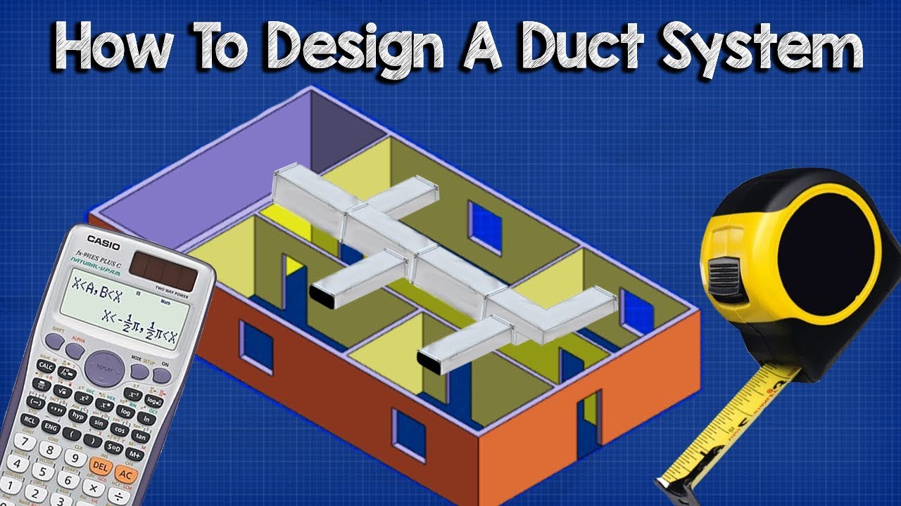
Ductwork sizing, calculation and design for efficiency - HVAC Basics + full worked example
video description
Date: 2023-11-17
Related videos




Comments and reviews: 30
Deekshith
Sir,
I have one query, When designing the HVAC supply duct system, After calculation of ASP from the manufacturer blower data (ESP- Device pressure losses. That ASP will become the pressure drop budget for the duct system.
Now if we are designing the duct system with equal friction method based on FR calculated. and carrying out CFD analysis of designed duct, the solver fetches static pressure and total pressure data w. r. t our design.
Now w. r. t previously calculated ASP which is our pressure drop budget, say some 0. 4 inches of water gauge.
Now inorder to check whether duct design is within the limits as per ASP in CFD analysis tools.
which pressure drop should I need to consider ( it's a total pressure in the volume of air or it's difference in Total pressure at inlet to outlets, or it's a max static pressure developed in the air volume inside duct)
kindly clarify
reply
Sir,
I have one query, When designing the HVAC supply duct system, After calculation of ASP from the manufacturer blower data (ESP- Device pressure losses. That ASP will become the pressure drop budget for the duct system.
Now if we are designing the duct system with equal friction method based on FR calculated. and carrying out CFD analysis of designed duct, the solver fetches static pressure and total pressure data w. r. t our design.
Now w. r. t previously calculated ASP which is our pressure drop budget, say some 0. 4 inches of water gauge.
Now inorder to check whether duct design is within the limits as per ASP in CFD analysis tools.
which pressure drop should I need to consider ( it's a total pressure in the volume of air or it's difference in Total pressure at inlet to outlets, or it's a max static pressure developed in the air volume inside duct)
kindly clarify
reply
John
I don't know a darn thing about HVAC but I do know maths. Towards the end, you discuss losses and using baffles to compensate. I don't see anything about the origination fan, it's CFM, and any filters throughout this system.
I would like to build out my own system originating from a window and a plenum box, where a blower is first, then a MERV or HEPA filter, followed with 4 UVC lamps. This system will only supply two rooms with a junction or collector as I call it, in-between both rooms (hallway) that is again supplied with a MERV or HEPA filter and UVC lamps out to the second room. Second room is much larger than the first originating room. Two exhausts, one inside origination window above and other through window of second room.
reply
I don't know a darn thing about HVAC but I do know maths. Towards the end, you discuss losses and using baffles to compensate. I don't see anything about the origination fan, it's CFM, and any filters throughout this system.
I would like to build out my own system originating from a window and a plenum box, where a blower is first, then a MERV or HEPA filter, followed with 4 UVC lamps. This system will only supply two rooms with a junction or collector as I call it, in-between both rooms (hallway) that is again supplied with a MERV or HEPA filter and UVC lamps out to the second room. Second room is much larger than the first originating room. Two exhausts, one inside origination window above and other through window of second room.
reply
al
Paul, regarding the simscale example, you mentioned that the red colored region which is the increase in velocity, causes the static pressure to rise. Wouldnt it be the opposite. Higher the velocity, lower the static pressure due to Bernoullis Principle. If you increase the velocity pressure then the static pressure should go down to balance the total pressure. I am confused because the increase in pressure drop also increases the static pressure did not make sense to me while comparing smooth and not smooth transitions. I am thinking the static pressure increase will happen on the upstream side of the flow, however, downstream side will loose pressure. Please correct me if I am wrong. Thank you.
reply
Paul, regarding the simscale example, you mentioned that the red colored region which is the increase in velocity, causes the static pressure to rise. Wouldnt it be the opposite. Higher the velocity, lower the static pressure due to Bernoullis Principle. If you increase the velocity pressure then the static pressure should go down to balance the total pressure. I am confused because the increase in pressure drop also increases the static pressure did not make sense to me while comparing smooth and not smooth transitions. I am thinking the static pressure increase will happen on the upstream side of the flow, however, downstream side will loose pressure. Please correct me if I am wrong. Thank you.
reply
Zakarya
Thanks for the video, very helpful! I have a question, while calculating the pressure drop in tees (14: 45) the pressure loss formula was used with the outlet velocity. However, in ASHRAE fundamentals book 2001, they state that for junctions, the pressure drop is referenced to the dynamic pressure drop for the common section (i. e, main section upstream. Therefore, for junctions, as far as I understand, the inlet velocity has to be used to calculate the pressure drop from the junction either the branched part or the straight part. could you please enlighten me on this?
reply
Thanks for the video, very helpful! I have a question, while calculating the pressure drop in tees (14: 45) the pressure loss formula was used with the outlet velocity. However, in ASHRAE fundamentals book 2001, they state that for junctions, the pressure drop is referenced to the dynamic pressure drop for the common section (i. e, main section upstream. Therefore, for junctions, as far as I understand, the inlet velocity has to be used to calculate the pressure drop from the junction either the branched part or the straight part. could you please enlighten me on this?
reply
Alen
Ok this is what I want to get into. Sounds really interesting. I currently have this oversized fan in my house. The duct looks waay too small and the noise is the biggest problem. I was thinking to increase the size of the duct to lower the noise but will try first to use these calculations to see if it would make any losses in terms of cooling. Do you (or anybody here in comment section) have any advices on how to lower the noise without loosing too much on cooling?
Thank you in advance.
reply
Ok this is what I want to get into. Sounds really interesting. I currently have this oversized fan in my house. The duct looks waay too small and the noise is the biggest problem. I was thinking to increase the size of the duct to lower the noise but will try first to use these calculations to see if it would make any losses in terms of cooling. Do you (or anybody here in comment section) have any advices on how to lower the noise without loosing too much on cooling?
Thank you in advance.
reply
JosyPtr
The Engineering Mindset: - I have have not under stand Fitting example H: Outlet direction 2-Bend (Time 15: 10 - 15: 48. Calculated Velocity ratio and Area ratio, then based on that get coefficient 0. 364 from bend table. My question is why don't we applied that coefficient value in pressure loss equation pressure loss=coefficient x density x velocity Sq. / 2. instead of that directly mention that vale 0. 364 as fitting loss in Direction G-I. Anyone
please help
reply
The Engineering Mindset: - I have have not under stand Fitting example H: Outlet direction 2-Bend (Time 15: 10 - 15: 48. Calculated Velocity ratio and Area ratio, then based on that get coefficient 0. 364 from bend table. My question is why don't we applied that coefficient value in pressure loss equation pressure loss=coefficient x density x velocity Sq. / 2. instead of that directly mention that vale 0. 364 as fitting loss in Direction G-I. Anyone
please help
reply
james
Ok my question which is better, a furnace register that blows upward or one that blows across the floor as I have noticed blowing across the floor has it problems and furniture can block flow and create cold spots especially in smaller rooms so I guess my question is do I heat from top down if that makes sense(my old house has registers in the wall and blow across the floor)
reply
Ok my question which is better, a furnace register that blows upward or one that blows across the floor as I have noticed blowing across the floor has it problems and furniture can block flow and create cold spots especially in smaller rooms so I guess my question is do I heat from top down if that makes sense(my old house has registers in the wall and blow across the floor)
reply
jeffsond
Thx! Question, I have a 440 sq ft hunting cabin. I have an electric furnace and a 1. 5 ton condenser. Can I use 12x 8 rectangular ductwork? There is a possibility long time from now the cabin could increase in size to 770 sq ft. This is a 1 level cabin. Ill be using 1 straight length of ductwork 36 long. 1- 4 branch to the restroom.
reply
Thx! Question, I have a 440 sq ft hunting cabin. I have an electric furnace and a 1. 5 ton condenser. Can I use 12x 8 rectangular ductwork? There is a possibility long time from now the cabin could increase in size to 770 sq ft. This is a 1 level cabin. Ill be using 1 straight length of ductwork 36 long. 1- 4 branch to the restroom.
reply
Yasuhiro
HI, I am a beginner, ducting for 2 story with basement in South Philadelphia,
the land / house space is Wide 16 ' x Long 40 ' (feets),
what is the ducting dimension / size for main duct, [ 8x16 ] or [ 8x24 ] or. is better?
because I do not know how to calculate it.
thank you
reply
HI, I am a beginner, ducting for 2 story with basement in South Philadelphia,
the land / house space is Wide 16 ' x Long 40 ' (feets),
what is the ducting dimension / size for main duct, [ 8x16 ] or [ 8x24 ] or. is better?
because I do not know how to calculate it.
thank you
reply
Mike
Amazing video, thank you. I noticed in the video (14. 39) you are inputting the data into the interpellation website. that you input in Q11 value 0. 14. Should it had been 0. 15? (LOL) Its just me and no big deal. It kept me on my toes. so very helpful on your part. Love the videos. THANK YOU
reply
Amazing video, thank you. I noticed in the video (14. 39) you are inputting the data into the interpellation website. that you input in Q11 value 0. 14. Should it had been 0. 15? (LOL) Its just me and no big deal. It kept me on my toes. so very helpful on your part. Love the videos. THANK YOU
reply
Shredded
As someone who has been doin HVAC design for a while, this is very helpful if youre trying to understand the theory and calculations for the design. But in the real world, no one is going to build ductwork like yours because everyone is cheap and prefers round taps and tee junctions.
reply
As someone who has been doin HVAC design for a while, this is very helpful if youre trying to understand the theory and calculations for the design. But in the real world, no one is going to build ductwork like yours because everyone is cheap and prefers round taps and tee junctions.
reply
education
I have a 420 square foot building with a furnace and a 19x12 x 4 foot plenum. I bought 16x8 rectangular ducts that run 24 foot long with six 6 vents. Are the ducts too big? Should I go with a 14x8 or a 12x8 duct size? I haven't installed the 16x8 yet so I could exchange it. Thanks.
reply
I have a 420 square foot building with a furnace and a 19x12 x 4 foot plenum. I bought 16x8 rectangular ducts that run 24 foot long with six 6 vents. Are the ducts too big? Should I go with a 14x8 or a 12x8 duct size? I haven't installed the 16x8 yet so I could exchange it. Thanks.
reply
solution
Hay engineer.
I have one hanger which has 7 room and 3 big hole.
How can manage and I select either split air condition and Centralaized cooling system.
Which system is efficient for me. plz note that all air condition is not working all the time unless the big holes.
reply
Hay engineer.
I have one hanger which has 7 room and 3 big hole.
How can manage and I select either split air condition and Centralaized cooling system.
Which system is efficient for me. plz note that all air condition is not working all the time unless the big holes.
reply
Hindricks
Good day Sir. May I asked what maybe the factors I should consider in computing cooling load by if I am going to use manual calculation?
My problem is that when using danfoss coolerselector2 (software) I am getting a different values which has a very big discrepancy.
reply
Good day Sir. May I asked what maybe the factors I should consider in computing cooling load by if I am going to use manual calculation?
My problem is that when using danfoss coolerselector2 (software) I am getting a different values which has a very big discrepancy.
reply
Jerome
Hi, thanks for this article. I used this method with the same pressure in all ducts from the main to all the branches with the quantity of air needed, I found out that some duct and branches fall below 2 m/sec. what will happen if I adjust the velocity and the pressure?
reply
Hi, thanks for this article. I used this method with the same pressure in all ducts from the main to all the branches with the quantity of air needed, I found out that some duct and branches fall below 2 m/sec. what will happen if I adjust the velocity and the pressure?
reply
education
Do we size the unit by heat load or volume flow rate at main duct A? I am running into a situation that unit capacity is sufficient to the heat load, but the calculated volume flow rate at main duct A is more than the unit CFM. What do I do in this case?
reply
Do we size the unit by heat load or volume flow rate at main duct A? I am running into a situation that unit capacity is sufficient to the heat load, but the calculated volume flow rate at main duct A is more than the unit CFM. What do I do in this case?
reply
boe
Loved the video - can you make one with Imperial measurements for your slower US brethren? :) You can say - oh just use feet vs. However if the video was done all the way through with measurements we'd likely use, it would be easier to follow.
reply
Loved the video - can you make one with Imperial measurements for your slower US brethren? :) You can say - oh just use feet vs. However if the video was done all the way through with measurements we'd likely use, it would be easier to follow.
reply
b1conis
The new job has the customer hire an engineer to design the system. Or, charge them to design the system from plans. I personally work with a lot of engineers and they do this all the time. If the customer wants a free design move on.
reply
The new job has the customer hire an engineer to design the system. Or, charge them to design the system from plans. I personally work with a lot of engineers and they do this all the time. If the customer wants a free design move on.
reply
CHOMAHOMA
This method is great. The problem is that I am in the US. and they use a very complicated system. They refuse to adapt to the metric system so they keep complicating themselves and everybody else in the industry.
reply
This method is great. The problem is that I am in the US. and they use a very complicated system. They refuse to adapt to the metric system so they keep complicating themselves and everybody else in the industry.
reply
Sri
why is a fan selected based on only index run pressure loss, what about all other pressure loss in other branches? fan need to pump air through the other branches right /? like pressure loss of AB+BC+DE+EF+EH+HL
reply
why is a fan selected based on only index run pressure loss, what about all other pressure loss in other branches? fan need to pump air through the other branches right /? like pressure loss of AB+BC+DE+EF+EH+HL
reply
Civil
Question: Why are two story homes, fitted with 2 units, but not ducted to accommodate 'convection'? Heat going up, cold falling. Returns are on the same floors as ducts for each unit. WHY?
reply
Question: Why are two story homes, fitted with 2 units, but not ducted to accommodate 'convection'? Heat going up, cold falling. Returns are on the same floors as ducts for each unit. WHY?
reply
Jake
Yeah this is pretty cool. Im a sheet metal apprentice, specializing in ductwork for commercial jobs. Interesting to see how the ductwork I make is designed and such. Great video!
reply
Yeah this is pretty cool. Im a sheet metal apprentice, specializing in ductwork for commercial jobs. Interesting to see how the ductwork I make is designed and such. Great video!
reply
jungapo2
can you also do a comparison of using one centralized hvac system versus mini-split units for the same size of a house having four bedroom and two floors. tks.
reply
can you also do a comparison of using one centralized hvac system versus mini-split units for the same size of a house having four bedroom and two floors. tks.
reply
Bluemou
Hi help please
In case we have an hrv or an erv the duct of return air coming out from wc where shall we connect it? Would we mix it with fresh air?
reply
Hi help please
In case we have an hrv or an erv the duct of return air coming out from wc where shall we connect it? Would we mix it with fresh air?
reply
Taylor
Are you interested in design HVAC system for a house Im building? Were planning on installing it so I cant find anyone to just design it for me
reply
Are you interested in design HVAC system for a house Im building? Were planning on installing it so I cant find anyone to just design it for me
reply
Ramz
Hi there Engineering Mindset! Your videos are all informative, do you have one for sizing of HVAC supply and return air grille? Thanks!
reply
Hi there Engineering Mindset! Your videos are all informative, do you have one for sizing of HVAC supply and return air grille? Thanks!
reply
Igor
Great video! Thanks for sharing!
One question: What about split systems? How can I size the ductwork? is it necessary?
reply
Great video! Thanks for sharing!
One question: What about split systems? How can I size the ductwork? is it necessary?
reply
Tony
Hi Paul. What a brilliant video thank you very much! Can you put a link to the Duct Pressure Loss Chart you used please?
reply
Hi Paul. What a brilliant video thank you very much! Can you put a link to the Duct Pressure Loss Chart you used please?
reply
Roxane
Delta T = 8 degrees celcius but in the computation it become 8 kelvin. how is that happened? please explain it to me
reply
Delta T = 8 degrees celcius but in the computation it become 8 kelvin. how is that happened? please explain it to me
reply
Kimjit
As an engineer, this has help me a lot. Thank you so much for teaching and making useful video like this. Dont stop!
reply
As an engineer, this has help me a lot. Thank you so much for teaching and making useful video like this. Dont stop!
reply
Add a review, comment
Other channel videos