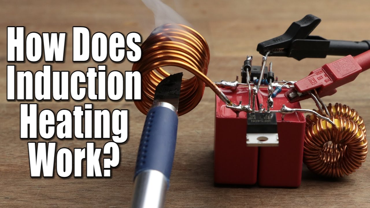
How does Induction Heating Work? DIY Induction Heater Circuit
video description
a. The tank LC circuit is a parallel circuit, so it has a high impedance at resonance and it must be matched and be fed from a high impedance current source, and this is how it does it.
b. The supply at Vcc looking back at it, is always a low output impedance voltage source between Vcc terminal and ground/ earth.
c. Each MOSFET is acting as a switch with ZERO impedance when ON, and HIGH impedance when OFF. They alternate this ON, OFF role.
d. The inductor which is used as a choke, connected between Vcc and drain of an ON MOSFET is an inductor connected across a DC VOLTAGE source so it will start charging up reasonably fast with a normal varying DC current.
e. When this DC charging inductive current is broken by the relevant MOSFET at one end, trying to breaking and switching it off with a HIgh impedance at its drain, then the charged current will try to be held constant and so the drain will go to a very high value to keep the current constant which is then routed and fed to one end of the parallel tank, high impedance LC circuit.
f. While the action in 'e' is taking place, the other end of the parallel tank circuit is connected to the ground through the ZERO, ON impedance, of the other MOSFET.
g. So when the MOSFET is on it is really acting as one terminal of a voltage source and when off the MOSFET is really redundant as Vcc acting as a voltage source has its current trough the Charged Choke inductor in series with Vcc, the tank circuit and the ON MOSFET where the series choke now acts as a current device to make the Vcc source act as a current source. It is this combination of connecting the choke to a voltage source and then switching it to supply the tank circuit with a high impedance constant current effect including a high voltage resulting due to the high impedance of the parallel tank circuit.
This is indeed a very ingenious circuit where the alternating role of voltage sources and current sources characteristics need to be fully understood very clearly.
Date: 2020-09-05
Related videos


Comments and reviews: 9
Luis
Hello my friend, great video and nice explanation. However, I am a little concerned about the aluminium (in particular, can you vary the frequency of your oscillator circuit in order to heat up the aluminium? or does the frequency not affect the results?
reply
Hello my friend, great video and nice explanation. However, I am a little concerned about the aluminium (in particular, can you vary the frequency of your oscillator circuit in order to heat up the aluminium? or does the frequency not affect the results?
reply
Lazaro
Hi Scott! Is this circuit potent enough to use in real cooking? If not, do you have a recommendation/ link of one with enough power for me? I plan to do a 4 coils cooking top for my new apartment. I'd be happy to show you when finished =D
reply
Hi Scott! Is this circuit potent enough to use in real cooking? If not, do you have a recommendation/ link of one with enough power for me? I plan to do a 4 coils cooking top for my new apartment. I'd be happy to show you when finished =D
reply
Scott
Howdy Scott, my name too btw! Where can I find a copy of the circuit diagram? I have looked at all the links in the description but none include a link to the diagram or gerber file.
Keep up the great work!
reply
Howdy Scott, my name too btw! Where can I find a copy of the circuit diagram? I have looked at all the links in the description but none include a link to the diagram or gerber file.
Keep up the great work!
reply
Jan
Hi GS, I am trying to make the heater board as small as possible. Could you tell me what is minimum voltage resistance for capacitors? Those red WIMAs that you put there are huge.
reply
Hi GS, I am trying to make the heater board as small as possible. Could you tell me what is minimum voltage resistance for capacitors? Those red WIMAs that you put there are huge.
reply
Sayali
Hi,
I want to build an induction heater of 2000Watts. is there any simple circuit by which I can use the AC supply directly to control power of induction heater?
reply
Hi,
I want to build an induction heater of 2000Watts. is there any simple circuit by which I can use the AC supply directly to control power of induction heater?
reply
Alejandro
Heee please!
Somebody Can tell me which inverter topoligy is that?
Or is not a inverter?
I belive that mosfet are always on am I right?
reply
Heee please!
Somebody Can tell me which inverter topoligy is that?
Or is not a inverter?
I belive that mosfet are always on am I right?
reply
keagan
Man we have a tool heat at work to hold carbide end mills and it heats up in about 4sec and use 11kw to do its crazy and works really well
reply
Man we have a tool heat at work to hold carbide end mills and it heats up in about 4sec and use 11kw to do its crazy and works really well
reply
Steve
I wish I did a degree in electrical engineering. I feel I wasted my life now that I am in my 50's and just getting into electronics.
reply
I wish I did a degree in electrical engineering. I feel I wasted my life now that I am in my 50's and just getting into electronics.
reply
FEBRI
hi Scott, I really like your video, can you see us the schematic of the induction you made. anyway thanks for the good explanation.
reply
hi Scott, I really like your video, can you see us the schematic of the induction you made. anyway thanks for the good explanation.
reply
Add a review, comment
Other channel videos