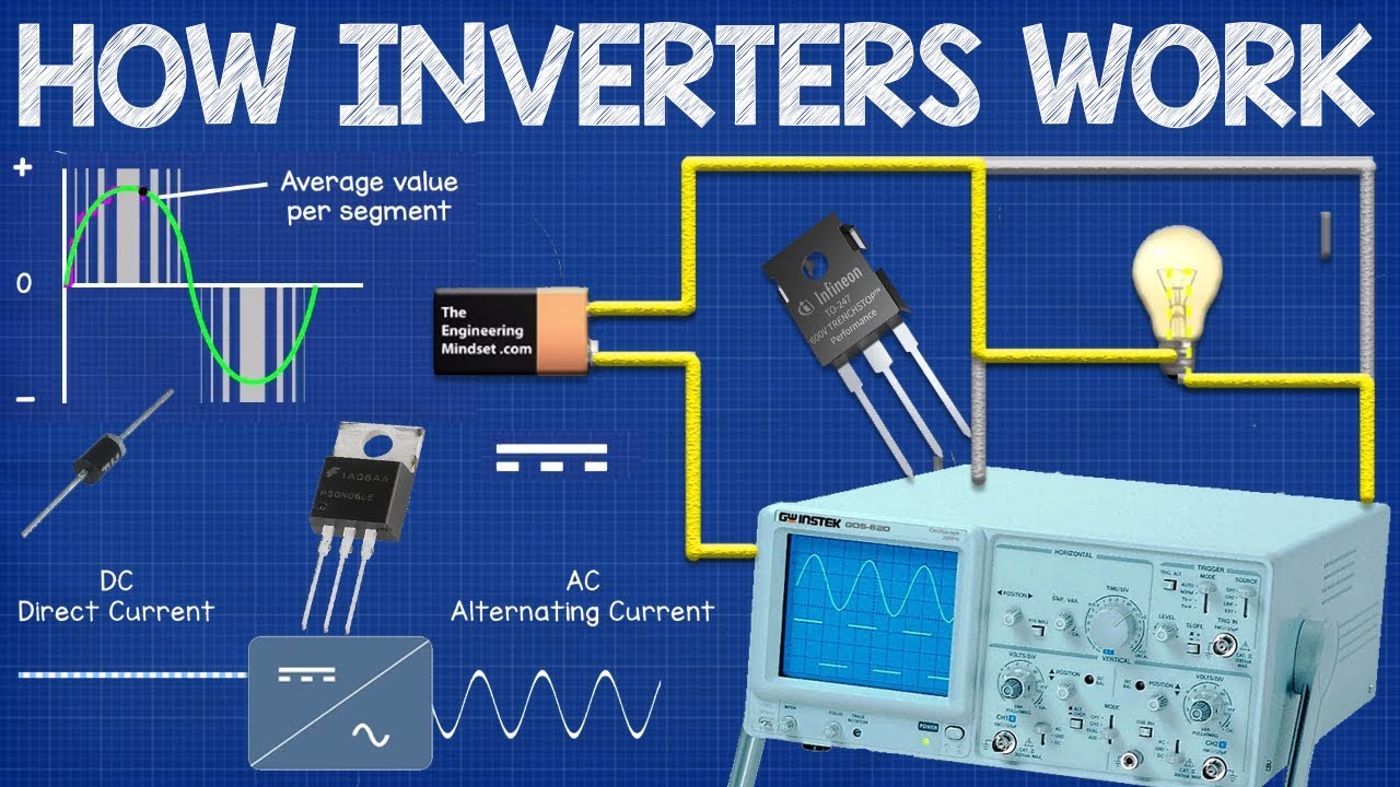
How Inverters Work - Working principle rectifier
video description
Date: 2023-11-17
Related videos


Comments and reviews: 30
Matrinique
I love your videos and how you explain things! Thank you for this series!
Could you make a video that explains how basic household appliances work? Things like a microwave, refrigerator, coffee machine, electric fan, or HVAC? I know it's basically converting electric energy into the specific kind of energy an appliance uses to do its job, but how does that conversion happen?
You explained light bulbs (lamps) as an example, and that's just electric current running through a wire of a specific material that produces light energy at a certain temperature.
EDIT: Just finished the video. That's amazinggggggggg why don't we learn about this stuff in school?
reply
I love your videos and how you explain things! Thank you for this series!
Could you make a video that explains how basic household appliances work? Things like a microwave, refrigerator, coffee machine, electric fan, or HVAC? I know it's basically converting electric energy into the specific kind of energy an appliance uses to do its job, but how does that conversion happen?
You explained light bulbs (lamps) as an example, and that's just electric current running through a wire of a specific material that produces light energy at a certain temperature.
EDIT: Just finished the video. That's amazinggggggggg why don't we learn about this stuff in school?
reply
daphn_im
My dad was an engineer and I've been really curious about how our solar panels work and he mentioned an inverter converting the voltage from the panels which I think was about 12 and comes out 220 to make our television work. He couldn't explain how inverters exactly does it so I've been searching for it. Since I dont study engineering (im still at highschool) I cant fully understand this but it gives me the idea how it really works maybe I should start learning the very basics before this
reply
My dad was an engineer and I've been really curious about how our solar panels work and he mentioned an inverter converting the voltage from the panels which I think was about 12 and comes out 220 to make our television work. He couldn't explain how inverters exactly does it so I've been searching for it. Since I dont study engineering (im still at highschool) I cant fully understand this but it gives me the idea how it really works maybe I should start learning the very basics before this
reply
William
An Important point that I would like to mention is that the identifying attribute of a DC is that it flows in one direction but, it is not always at it's peak. For learning purposes, ommiting the fact that DC can fluctuate at specific frequencies and transmit data signals is convenient as to not confuse new learners. Although, to say that DC is always at it's maximum is simply not correct as a definition.
Great content btw! Glad you are able to make such excellent educational videos.
reply
An Important point that I would like to mention is that the identifying attribute of a DC is that it flows in one direction but, it is not always at it's peak. For learning purposes, ommiting the fact that DC can fluctuate at specific frequencies and transmit data signals is convenient as to not confuse new learners. Although, to say that DC is always at it's maximum is simply not correct as a definition.
Great content btw! Glad you are able to make such excellent educational videos.
reply
Luca
Actually PWM for ac motors works in a slightly different way. Since lowering the power won't affect the speed of the motor but just the torque PWM works on the frequency it does something like sending a full positive wave skipping the next negative, the next positive and then sending the next negative. it kinda allows one half of the wave form stops the next 2 allows the 3rd and so on. this way the frequency is basically reduced to 1/3 from 50hz to something like 18 hz slowing down the motor
reply
Actually PWM for ac motors works in a slightly different way. Since lowering the power won't affect the speed of the motor but just the torque PWM works on the frequency it does something like sending a full positive wave skipping the next negative, the next positive and then sending the next negative. it kinda allows one half of the wave form stops the next 2 allows the 3rd and so on. this way the frequency is basically reduced to 1/3 from 50hz to something like 18 hz slowing down the motor
reply
Louis
Are you old enough to remember the old fashioned vibrators that were used in tube car radios of the fifties? Your beginning illustration shows how the vibrator worked. The one of the output fed a step up transformer, the a second set of switches would take the output of the transformer would then be used to un-alternate the output of the step up transformers to feed the filtering network then to the tubes. Selenium and silicon solid state rectifiers did no exist at that time!
reply
Are you old enough to remember the old fashioned vibrators that were used in tube car radios of the fifties? Your beginning illustration shows how the vibrator worked. The one of the output fed a step up transformer, the a second set of switches would take the output of the transformer would then be used to un-alternate the output of the step up transformers to feed the filtering network then to the tubes. Selenium and silicon solid state rectifiers did no exist at that time!
reply
Martyn
good video, but my inverter turned off while abroad for 12 months, when I got back the fault light was on and the inverter Tripp had turned off. After I put the trip back on the Battery back up and the charging system was not working. I have been it with the manufacture but they have told me it's out of guarantee this would have been in less than 4 years so far I have not been able to get the problem sorted, with lots of installers but no proper engineers can you help me?
reply
good video, but my inverter turned off while abroad for 12 months, when I got back the fault light was on and the inverter Tripp had turned off. After I put the trip back on the Battery back up and the charging system was not working. I have been it with the manufacture but they have told me it's out of guarantee this would have been in less than 4 years so far I have not been able to get the problem sorted, with lots of installers but no proper engineers can you help me?
reply
Eric
The converter is not an inverter even thought it could be but two terms are not used interchangeably. Inverter two types digital and analog. Digital is like the Q and J output: the Q output the supposed resulted and the J is the reverse of that while the analog is that it take the sign wave input and shift 180 degree phase angle to create an opposite of the input and out put it to cool the ambient attack signal or to cool extreme high temperature by communication effect
reply
The converter is not an inverter even thought it could be but two terms are not used interchangeably. Inverter two types digital and analog. Digital is like the Q and J output: the Q output the supposed resulted and the J is the reverse of that while the analog is that it take the sign wave input and shift 180 degree phase angle to create an opposite of the input and out put it to cool the ambient attack signal or to cool extreme high temperature by communication effect
reply
Donna
Question: I have a inverter in my refrigerator that is grounded, which appears on the wiring diagram to be grounded in the fridge itself plus the fridge is grounded in a dedicated circuit. I'm getting fluctuating 9-43v from house ground to earth ground. Could this inverter be causing this as the inverter modulates the compressor speed acting like a french ground? I have checked the wiring from the panel, all is new and secure and the fridge runs as normal.
reply
Question: I have a inverter in my refrigerator that is grounded, which appears on the wiring diagram to be grounded in the fridge itself plus the fridge is grounded in a dedicated circuit. I'm getting fluctuating 9-43v from house ground to earth ground. Could this inverter be causing this as the inverter modulates the compressor speed acting like a french ground? I have checked the wiring from the panel, all is new and secure and the fridge runs as normal.
reply
shinjikok
Nice explanation, Correct me if I'm wrong.
INVERTER AIRCON convert the AC to DC then back to AC power source (with the help of IGPT to manipulate the Sine Wave frequency) to run the air con compressor motor at different speed (similar to DC Fan)
NON-INVERTER AIRCON powered by AC will run by constant frequency Sine Wave power source. Its' compressor motor will run on full speed thus consume more electricity?
reply
Nice explanation, Correct me if I'm wrong.
INVERTER AIRCON convert the AC to DC then back to AC power source (with the help of IGPT to manipulate the Sine Wave frequency) to run the air con compressor motor at different speed (similar to DC Fan)
NON-INVERTER AIRCON powered by AC will run by constant frequency Sine Wave power source. Its' compressor motor will run on full speed thus consume more electricity?
reply
Malek
hi i have a problem with the output of my EPEVER UPOWER inverter/charger 230v 50Hz
i correctly connected my inverter to ground but when i test with a multimeter i have 115 volts between neutral and ground also 115 volts between live and ground!
Is it dangerous?
what is the problem and what is the solution?
And what about ground neutral bount?
Thanks for your help
reply
hi i have a problem with the output of my EPEVER UPOWER inverter/charger 230v 50Hz
i correctly connected my inverter to ground but when i test with a multimeter i have 115 volts between neutral and ground also 115 volts between live and ground!
Is it dangerous?
what is the problem and what is the solution?
And what about ground neutral bount?
Thanks for your help
reply
Rob
Thank you for this video but I fear it's unnecessarily complicated where it doesn't need to be. Here's what I would cut for being unnecessarily complex:
3: 15-4: 27 Beginners don't need to know this; confusing. Save for the hypothetical lesson 2
6: 09 forward - Why? Much too complex! Please just show me how the inverter in my car works, this is FAR too advanced.
Thanks.
reply
Thank you for this video but I fear it's unnecessarily complicated where it doesn't need to be. Here's what I would cut for being unnecessarily complex:
3: 15-4: 27 Beginners don't need to know this; confusing. Save for the hypothetical lesson 2
6: 09 forward - Why? Much too complex! Please just show me how the inverter in my car works, this is FAR too advanced.
Thanks.
reply
juggerfox
Hi, at 7: 05, I don't get how the graph on the left shows positive voltage being fed into the motor with the respective switches closed and then switches to negative voltage but the same switches are still being closed. How do make the DC flow in the opposite direction if the same path is being used?
reply
Hi, at 7: 05, I don't get how the graph on the left shows positive voltage being fed into the motor with the respective switches closed and then switches to negative voltage but the same switches are still being closed. How do make the DC flow in the opposite direction if the same path is being used?
reply
Jayesh
Sir if we are using single transformer for inverting and charging the battery back how the mosfet will work as switch and rectifier. Please explain. My question is to find answer for the new direct start methods in bike engines which use same single coil as starting motor and charging alternator.
reply
Sir if we are using single transformer for inverting and charging the battery back how the mosfet will work as switch and rectifier. Please explain. My question is to find answer for the new direct start methods in bike engines which use same single coil as starting motor and charging alternator.
reply
Mathew
With electric motors the ac courent, yes, gets peshed by the peak valley combination so indede alternating the frequency and intensity does indeed change the speed. Alternators are yes 3 phase. 4 phase was experimented with but they have been found to b ineficiant.
reply
With electric motors the ac courent, yes, gets peshed by the peak valley combination so indede alternating the frequency and intensity does indeed change the speed. Alternators are yes 3 phase. 4 phase was experimented with but they have been found to b ineficiant.
reply
Ethan
But i thought all things use dc at the end, so the ac appliances use a rectifier to convert the ac to dc i thought? I am confused, if i am correct is it done this way to control phase frequency and other things? Or am i wrong? Thanks!
reply
But i thought all things use dc at the end, so the ac appliances use a rectifier to convert the ac to dc i thought? I am confused, if i am correct is it done this way to control phase frequency and other things? Or am i wrong? Thanks!
reply
Andrew
Amazing. I install these heat pumps and have been to several of the manufacturers training seminars. I still never understood what was going on, why they where called inverters or what pwm was used for. This makes sense to me now.
reply
Amazing. I install these heat pumps and have been to several of the manufacturers training seminars. I still never understood what was going on, why they where called inverters or what pwm was used for. This makes sense to me now.
reply
Mikey
Very great videos! Only thing that may help non-engineers (by trade) is the pacing of the video can be fast between topics and main points for this processing the information. Really love the presentation and explanations. Thanks!
reply
Very great videos! Only thing that may help non-engineers (by trade) is the pacing of the video can be fast between topics and main points for this processing the information. Really love the presentation and explanations. Thanks!
reply
Luke
If I've understood correctly, I think the animation should show the top of the first half bridge and the bottom of the last half bridge switching when the waveform polarity is negative?
reply
If I've understood correctly, I think the animation should show the top of the first half bridge and the bottom of the last half bridge switching when the waveform polarity is negative?
reply
Solar
You know I try this with some mosfet but all the mosfet did was burn it self up instead of switching on and on with the spwm drive 50 hz but I believe I get some bad mosfet
reply
You know I try this with some mosfet but all the mosfet did was burn it self up instead of switching on and on with the spwm drive 50 hz but I believe I get some bad mosfet
reply
Palat
Good explanation and great presentation.
Please give me a clear explanation on example a 5V bridge rectifier. Also about a transformer less power supply.
reply
Good explanation and great presentation.
Please give me a clear explanation on example a 5V bridge rectifier. Also about a transformer less power supply.
reply
Thndr_
So how many times do the pulse switches need to change in order to mimic the sine wave? And why does having sharp changes in power damage AC electronics?
reply
So how many times do the pulse switches need to change in order to mimic the sine wave? And why does having sharp changes in power damage AC electronics?
reply
Anvilshock
5: 47 WRONG! A full cycle comprises TWO reversals, so a 50-Hz or a 60-Hz current reverses direction 100 or 120 times per second!
reply
5: 47 WRONG! A full cycle comprises TWO reversals, so a 50-Hz or a 60-Hz current reverses direction 100 or 120 times per second!
reply
education
It is a Shame that Most USA public school systems do NOT actually Cover this at all. Time to change the whole superstructure
reply
It is a Shame that Most USA public school systems do NOT actually Cover this at all. Time to change the whole superstructure
reply
Mahyar
I found the video super useful. I just wanna ask how can i implement pwm control on this with arduino? Please let me know!
reply
I found the video super useful. I just wanna ask how can i implement pwm control on this with arduino? Please let me know!
reply
hbib
I didn't understand how the lamps illuminate frome the battery through the negative pol when it was branched with 4 switches
reply
I didn't understand how the lamps illuminate frome the battery through the negative pol when it was branched with 4 switches
reply
Alinda
I wish all schools could be teaching like you we would be having an advanced civilization visiting mars like in a backyard
reply
I wish all schools could be teaching like you we would be having an advanced civilization visiting mars like in a backyard
reply
education
When people create content that shoot for this >>>>>>> Thank you from the bottom of my Heart. You did a very good Job!
reply
When people create content that shoot for this >>>>>>> Thank you from the bottom of my Heart. You did a very good Job!
reply
Immortal
What? Just when it was getting interesting! Okay, I give up, you guys win - time for me to learn electronics!
reply
What? Just when it was getting interesting! Okay, I give up, you guys win - time for me to learn electronics!
reply
Kyle
Electrical workers learn about full and half rectifiers, whereas plumbers learn about full and half rectumfires.
reply
Electrical workers learn about full and half rectifiers, whereas plumbers learn about full and half rectumfires.
reply
theodore
It is helpful, but I would like a component by component breakdown with the math. Where might I find that?
reply
It is helpful, but I would like a component by component breakdown with the math. Where might I find that?
reply
Add a review, comment
Other channel videos


 13:39
13:39