Half Wave Rectifier Explained - power electronics
video description
circuit seen from 2007, that was secondary side of
Inverter of 120VAC connected on each output line single diodes that are
opposite polarity each facing, going to resistor load? Is this still a
portion of 120V AC output, or approx 40 volt half wave DC plus and minus
DC? The writer may have been thinking about back flow protection. This
is not print error, or about clipping circuit. Please advise.
Date: 2023-11-17
Related videos


Comments and reviews: 9
ZAHILAWATI
Key Takeaways for quick navigation:
00: 00 Diodes allow current in one direction, used for controlling current direction.
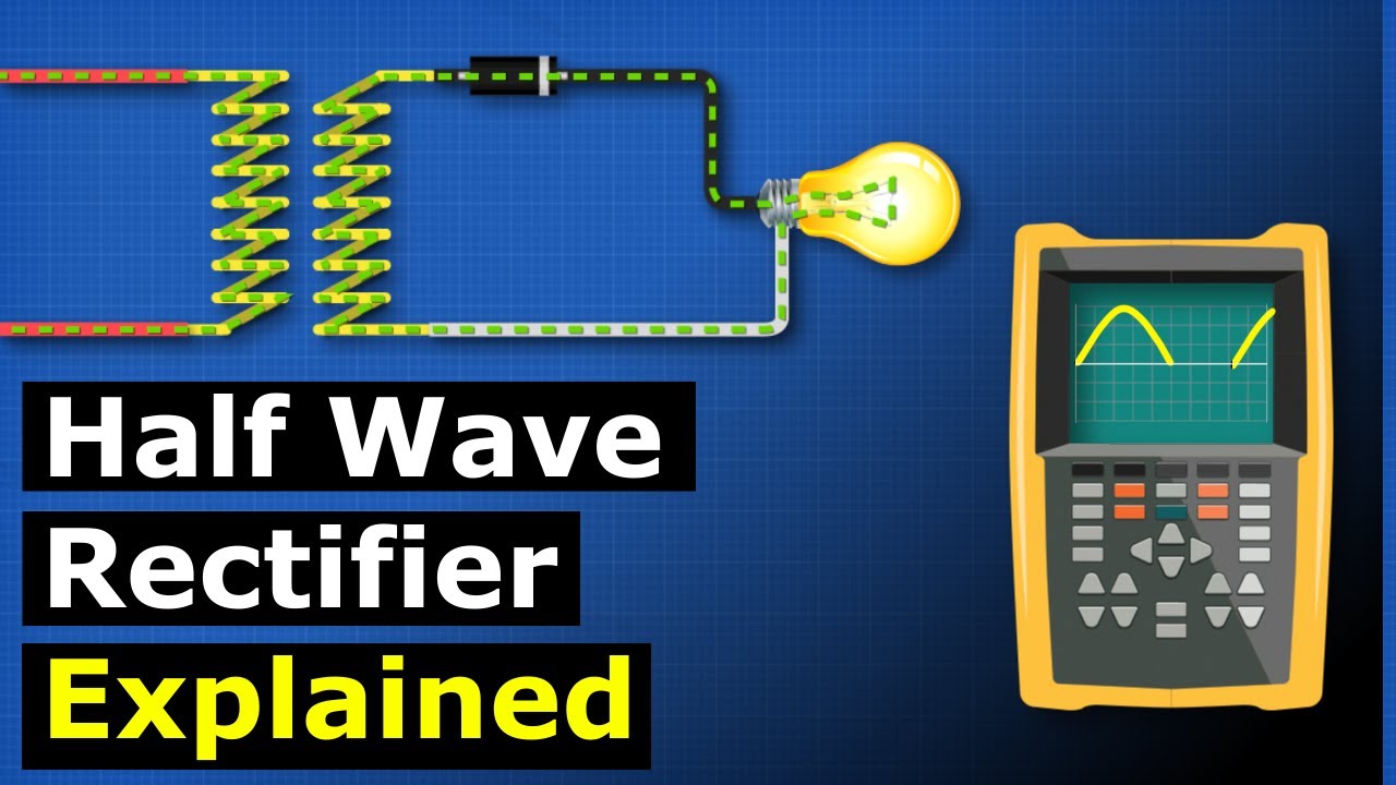
01: 27 Half-wave rectifier converts AC to pulsating DC using diodes.
02: 21 Diode blocks half of AC waveform, limiting power for devices.
02: 49 Half-wave rectification suitable for simple circuits, not electronics.
03: 03 Full-wave rectifier and additional components improve output quality.
Made with HARPA AI
reply
Key Takeaways for quick navigation:
00: 00 Diodes allow current in one direction, used for controlling current direction.
01: 27 Half-wave rectifier converts AC to pulsating DC using diodes.
02: 21 Diode blocks half of AC waveform, limiting power for devices.
02: 49 Half-wave rectification suitable for simple circuits, not electronics.
03: 03 Full-wave rectifier and additional components improve output quality.
Made with HARPA AI
reply
waterfuel
Question? - I have circuit diagram from 2005-2008. It has DC to AC Inverter of 120v AC output hooked with diode on each secondary line, that is reversed polarity ( Both different) one way, then other way. My test meter reads both on AC and DC. How do I get proper reading across load resistor on multi meter? This is not supposed to be clipping circuit of very low voltage. Circuit load on paper was inductor coil, diodes and and resistor.
reply
Sangeeth
This is super cool! The way everything is explained makes it easy to understand the concept. Can you please make a video explaining the difference between a +VE and -VE power sources? Like +12, -12, +5, -5 etc? What is the real life difference in it? What is it's significance? Why can't a +5V rated semiconductor device work when supplied with a -5V? And still a normal bulb works just fine?
reply
alun
I was thinking of using this to reduce power consumption for low powered lighting. So no current in bottom wave form technical using half the power. Will not notice the effect on lighting. I must put this to the test with say 2 or 3 60watt lamps.
reply
I was thinking of using this to reduce power consumption for low powered lighting. So no current in bottom wave form technical using half the power. Will not notice the effect on lighting. I must put this to the test with say 2 or 3 60watt lamps.
reply
Death
If we compare electricity with water and wires with pipes, than what's a diode in this scenario? It may be silly question, but it helps me to understand electricity more clearly or may be i am doing it wrong all along. Thank You. [DiowE]
reply
If we compare electricity with water and wires with pipes, than what's a diode in this scenario? It may be silly question, but it helps me to understand electricity more clearly or may be i am doing it wrong all along. Thank You. [DiowE]
reply
Beast
why is my lecturer showing this as the most complicated circuit ive seen in my life. can anyone tell me if this video is too simple
reply
why is my lecturer showing this as the most complicated circuit ive seen in my life. can anyone tell me if this video is too simple
reply
QueraTheGoat
you are saving lives man. you'l be seeing a lot of my comments on this journey of studying engineering. thank you
reply
you are saving lives man. you'l be seeing a lot of my comments on this journey of studying engineering. thank you
reply
D. Thamarai
Hi, can you try to make a ac voltage dimmer using triac and Arduino.
Because it will be very helpful to me.
reply
Hi, can you try to make a ac voltage dimmer using triac and Arduino.
Because it will be very helpful to me.
reply
Info
So what is benefit of diode?
Ok we can use it for DC
But
Where we can it use for commercial purpose?
reply
So what is benefit of diode?
Ok we can use it for DC
But
Where we can it use for commercial purpose?
reply
Add a review, comment
Other channel videos