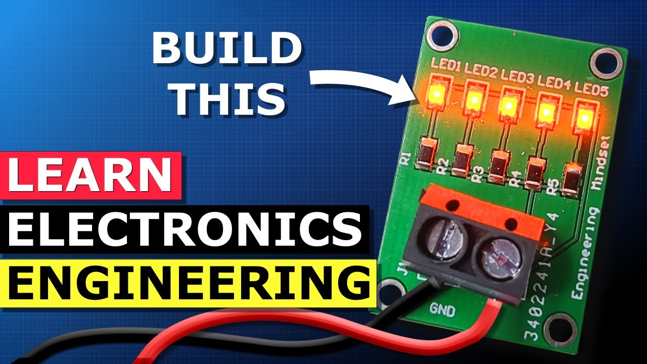
Design and Build a PCB - SMD LED Learn electronics engineering
video description
Date: 2023-11-17
Related videos


Comments and reviews: 23
DMXHindiGaming
Sir i have one question -
If I want to get 12v out of 24v 1amps transformer then how much rated resistors I need to subtract 12v out of it my load is a motor of 12v and it's max current is 1. 2amps and by my calculation I get 10ohm and 14. 4watt of resistors and i feel that this is wrong please help me sir
reply
Nejendary
Why is the circuit connected to. Each other in parallel circuit would it conflict the electrical flow shouldn't there just be 1 live wire to another neutral line from 1 resistor or capacitor to the rest of thr LEDS using radial circuit? canyone have any free stuff online about parallel circuits?
reply
Dejwid
I'm learning electronic engineering in school and your videos are awesome as well as your teaching method you shouls teach in schools! I also really love the way of showing how an circuit works on an example of water pipes! Keep doing your job man!
reply
I'm learning electronic engineering in school and your videos are awesome as well as your teaching method you shouls teach in schools! I also really love the way of showing how an circuit works on an example of water pipes! Keep doing your job man!
reply
Lofi
I am the student of Electronic and communication
I watch your daily to 12th and now I am in second year to be com like you
I feel your passion and understanding
And I want to be like you
Tnkss for detailing the video
reply
I am the student of Electronic and communication
I watch your daily to 12th and now I am in second year to be com like you
I feel your passion and understanding
And I want to be like you
Tnkss for detailing the video
reply
Pavel
at 4: 20 resistor is behind that bulb relative to the flow of electrons, does it matter where we put in resistors? I thought if you put it behind the build relative to the flow of electrons, the bulb will be burnt.
reply
at 4: 20 resistor is behind that bulb relative to the flow of electrons, does it matter where we put in resistors? I thought if you put it behind the build relative to the flow of electrons, the bulb will be burnt.
reply
Pavel
Buck would bee a better option, batteries get slowly depleted, led goes dimmer and dimmer, mr. Rimmer. edit: so many resistors, so many wasted energy by heat. why not using only one, just past the battery?
reply
Buck would bee a better option, batteries get slowly depleted, led goes dimmer and dimmer, mr. Rimmer. edit: so many resistors, so many wasted energy by heat. why not using only one, just past the battery?
reply
Leonidas
Hello, you have ordered the PCB and components, and assembled yourself, could you order the PCB already assembled by the manufacturer of PCB, . so only connected power and you are good to go. ?
reply
Hello, you have ordered the PCB and components, and assembled yourself, could you order the PCB already assembled by the manufacturer of PCB, . so only connected power and you are good to go. ?
reply
VariantAEC
1: 30 How many objects can you spot?
B4 - red LED bulb
D3 - metal nut
D1 - micro LED
F2 - unidentified (electronic element)
Viewport - 2560x1440
Video resolution - 854x480
reply
1: 30 How many objects can you spot?
B4 - red LED bulb
D3 - metal nut
D1 - micro LED
F2 - unidentified (electronic element)
Viewport - 2560x1440
Video resolution - 854x480
reply
DIY
B4, D1, D3, F2. I think that is it from what I can see in the Grid view area. That is all my eyes can pick up and using my wifes glasses all I can see. Unless I'm missing something.
reply
B4, D1, D3, F2. I think that is it from what I can see in the Grid view area. That is all my eyes can pick up and using my wifes glasses all I can see. Unless I'm missing something.
reply
Tyler
why are circuits designed with the switch and resistor before the load (like an led) if the electron flow is coming from the negative side of the battery towards the positive?
reply
why are circuits designed with the switch and resistor before the load (like an led) if the electron flow is coming from the negative side of the battery towards the positive?
reply
TUCW
A better way to solder those tiny smt components is to use a hot plate or a clothes iron with the hot side facing up. Some components could be damaged by a heat gun.
reply
A better way to solder those tiny smt components is to use a hot plate or a clothes iron with the hot side facing up. Some components could be damaged by a heat gun.
reply
GOD
Thanks. Great little video! More start to finish pcb circuit design videos like this (although more advanced circuits) would be appreciated! Thanks in advance!
reply
Thanks. Great little video! More start to finish pcb circuit design videos like this (although more advanced circuits) would be appreciated! Thanks in advance!
reply
engineering_mindset
01: 33 I know my eyes are already starting to go from too much computer screen time, but I see objects in squares B4, D3, F2, and I _think_ D1.
reply
01: 33 I know my eyes are already starting to go from too much computer screen time, but I see objects in squares B4, D3, F2, and I _think_ D1.
reply
JK
Being parallel couldn't you use one resistor before it branches off since the resistor had a plenty high enough rating for all the LEDs? Saving parts and time
reply
Being parallel couldn't you use one resistor before it branches off since the resistor had a plenty high enough rating for all the LEDs? Saving parts and time
reply
Ola007
Question please: Why didnt you use just one resistor and connect all the SMDs across it?
Did you use one resistor for each SMD for extra protection?
reply
Question please: Why didnt you use just one resistor and connect all the SMDs across it?
Did you use one resistor for each SMD for extra protection?
reply
Jason
I want to make a super simple Wireless system to light up a micro LED. I'll be building it out on a testing breadboard. What parts do I need?
reply
I want to make a super simple Wireless system to light up a micro LED. I'll be building it out on a testing breadboard. What parts do I need?
reply
hjs
Is it better to use registers for each leds rather than use single register for single input voltage in this case (all leds need same voltage)?
reply
Is it better to use registers for each leds rather than use single register for single input voltage in this case (all leds need same voltage)?
reply
NERO
can you make a pcb for controlling rgb with a macro controller? or maybe a 1 key macro switch? this kind of vids helps a lot for noobs
reply
can you make a pcb for controlling rgb with a macro controller? or maybe a 1 key macro switch? this kind of vids helps a lot for noobs
reply
Balaz
Finally a tutorial that does not flail around creation & design of custom PCB dedicated to steer the space ship. Thank you. +1
reply
Finally a tutorial that does not flail around creation & design of custom PCB dedicated to steer the space ship. Thank you. +1
reply
wevenhuis
I didn't see any solder on the smd components. Where did the solder come from when heating the components with a heatgun?
reply
I didn't see any solder on the smd components. Where did the solder come from when heating the components with a heatgun?
reply
SleepLess
Your video gave me an understanding of the SMD than the 2 hours of electronics engineering lecture I took in 10 mins XD
reply
Your video gave me an understanding of the SMD than the 2 hours of electronics engineering lecture I took in 10 mins XD
reply
Jasmarkelina
My last comment was kinda embrassing to be honest, but hey, atleast I learned something new, thanks again!
reply
My last comment was kinda embrassing to be honest, but hey, atleast I learned something new, thanks again!
reply
REB
Hello sir, can a 12v generator can be connected to a inverter and make it stable power supply for appliances?
reply
Hello sir, can a 12v generator can be connected to a inverter and make it stable power supply for appliances?
reply
Add a review, comment
Other channel videos