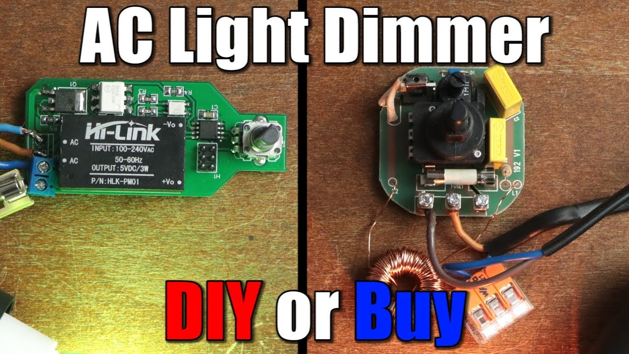
AC Light Dimmer DIY or Buy Phase Angle Control Tutorial
video description
Date: 2020-09-05
Related videos


Comments and reviews: 9
Daniel
I like the way you can go from an idea to a very professional looking pub board in such a short time. I can use my Laserjet printer and hi-gloss paper to print and etch a board but where I cut the board and drill my holes doesn't look that good, and I can't silkscreen. I look forward to designing my first pcb and having the board made professionally.
reply
Creations
Good job with the isolation on that thing, however one thing I do frown upon is the way you solder SMD component. There are better ways to to perform such a task without leaving so much solder in the pads. Maybe try using solder paste and a heat gun, or try dragging a small amount of solder across the pins of the ICs. Anyway, good job!
reply
Meli
Gosh I wish I was as smart as you. Im studying electronic engineering Im actually doing my thesis but I cant do what you do? I understand what you say & explain but I have no idea how I would do it by myself. maybe I shouldnt have studied what I did
reply
Gosh I wish I was as smart as you. Im studying electronic engineering Im actually doing my thesis but I cant do what you do? I understand what you say & explain but I have no idea how I would do it by myself. maybe I shouldnt have studied what I did
reply
Sayyed
Will this dimmer work for Fan regulation?
Actually, I tried it with the same solution that you have made but the only problem is humming noise is coming.
What things I can add to this circuit to make it noise-free?
reply
Will this dimmer work for Fan regulation?
Actually, I tried it with the same solution that you have made but the only problem is humming noise is coming.
What things I can add to this circuit to make it noise-free?
reply
Jadi
10: 10 why did you both uploading the bootloader. That adds a delay to starting up the program you have written. The bootloader adds a startup delay and is not necessary when flashing the chip over isp
reply
10: 10 why did you both uploading the bootloader. That adds a delay to starting up the program you have written. The bootloader adds a startup delay and is not necessary when flashing the chip over isp
reply
soundspark
I suppose you could have redesigned the board so there is good isolation distance between the mains voltage parts and the 5V circuit; that little power supply is isolated, correct?
reply
I suppose you could have redesigned the board so there is good isolation distance between the mains voltage parts and the 5V circuit; that little power supply is isolated, correct?
reply
Djaber
Hi, thank you so much for this great explanation
Just a simple question, this circuit that you just built, is it suitable to use with an inductive load, like a vibratory feeder?
reply
Hi, thank you so much for this great explanation
Just a simple question, this circuit that you just built, is it suitable to use with an inductive load, like a vibratory feeder?
reply
Sebastian
I'd like that you create an ac voltage regulator for example if the voltage step down from 110v it keeps steady and if it goes up, it keeps it steady as well
reply
I'd like that you create an ac voltage regulator for example if the voltage step down from 110v it keeps steady and if it goes up, it keeps it steady as well
reply
Miguel
Isn't the schematic wrong? The lamp would turn on even if the triac is off, it has a conducting path through the resistor, potentiometer and capacitor.
reply
Isn't the schematic wrong? The lamp would turn on even if the triac is off, it has a conducting path through the resistor, potentiometer and capacitor.
reply
Add a review, comment
Other channel videos