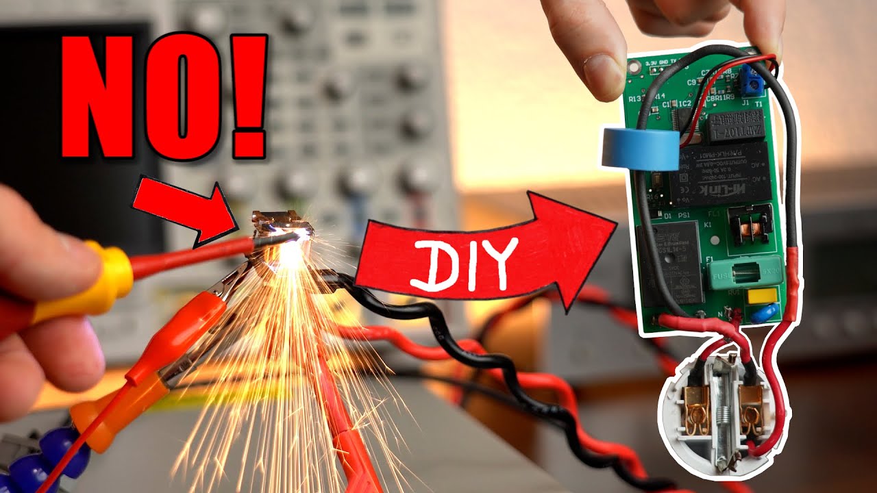
The Dark Secret of Smart Sockets and How I Fixed it! (DIY or Buy)
video description
Date: 2022-10-16
Related videos


Comments and reviews: 15
deepblueskyshine
You are free to steal from years of experience and production that came from times long before you were born. If you look inside power regulators of nowadays starting to disappear mains handheld power tools, especially in cheap or very old ones consisting of simple triac phase regulator without feedback IC you'll notice that in maximum position there is a simple switch that shorts triac thus avoiding unnessecary heating of the component. This fact may look unrelated at first read, but further on you can dig schematics for hydrophore pumps and water heating circulation pums switching blocks of famous for their reliability danish company Grundfos. For pums with fixed power the schematics consist of a triac operated via zero-crossing detection optocoupler ICs that guarantees no sparking and no grid noise and with some delay enough for the pump to get to the full power a relay shunts the triac. Shutting down the pump happens in reverse order - the relay switches off and in the moment of zero crossing triac turns off. Thus no switching noise or sparking that erodes relay contacts occurs during switching on and off and in this way they also achieve maximum durability.
reply
You are free to steal from years of experience and production that came from times long before you were born. If you look inside power regulators of nowadays starting to disappear mains handheld power tools, especially in cheap or very old ones consisting of simple triac phase regulator without feedback IC you'll notice that in maximum position there is a simple switch that shorts triac thus avoiding unnessecary heating of the component. This fact may look unrelated at first read, but further on you can dig schematics for hydrophore pumps and water heating circulation pums switching blocks of famous for their reliability danish company Grundfos. For pums with fixed power the schematics consist of a triac operated via zero-crossing detection optocoupler ICs that guarantees no sparking and no grid noise and with some delay enough for the pump to get to the full power a relay shunts the triac. Shutting down the pump happens in reverse order - the relay switches off and in the moment of zero crossing triac turns off. Thus no switching noise or sparking that erodes relay contacts occurs during switching on and off and in this way they also achieve maximum durability.
reply
Zygfryd
I am 100% with you - I recently replaced all my cheap boards I bought on Ali (with blue relays, SONGLE) that were almost all sticky, to the new ones - FANHAR - and these are with AgSnO2. Btw good companies use exactly FANHAR relays. It is not easy to find the 5V ones (black, FANHAR) but I back ordered 100 pieces on LCSC. And the cost of FANHAR is just about 0. 5 /piece
P. S.
your solution is kindly 4x more expensive than the good sockets i. e. from Athom and they use AgSnO2 relays, that are also providing power measurements and are based on ESP so super easy with ESPhome
reply
I am 100% with you - I recently replaced all my cheap boards I bought on Ali (with blue relays, SONGLE) that were almost all sticky, to the new ones - FANHAR - and these are with AgSnO2. Btw good companies use exactly FANHAR relays. It is not easy to find the 5V ones (black, FANHAR) but I back ordered 100 pieces on LCSC. And the cost of FANHAR is just about 0. 5 /piece
P. S.
your solution is kindly 4x more expensive than the good sockets i. e. from Athom and they use AgSnO2 relays, that are also providing power measurements and are based on ESP so super easy with ESPhome
reply
Ben
Impressive work! Depending on the plastic used (anything printable would tend to be an issue) I'd be just as concerned about the fire safety risks of the printed DIY case as I would've been with the possible downsides of the original commercial design in the typical use cases. The takeaway that cheap IoT devices have issues is important, but this is not something most people should DIY. It can be hard to identify which commercial products are decent, but they exist and are generally a better choice than DIY for this type of application.
reply
Impressive work! Depending on the plastic used (anything printable would tend to be an issue) I'd be just as concerned about the fire safety risks of the printed DIY case as I would've been with the possible downsides of the original commercial design in the typical use cases. The takeaway that cheap IoT devices have issues is important, but this is not something most people should DIY. It can be hard to identify which commercial products are decent, but they exist and are generally a better choice than DIY for this type of application.
reply
fatfox
I really appreciate your efforts and I like this video. Creating independent solutions for the proprietary smart home jungle could not be honored enough but for the comparison the time for the design process of circuit, board, case and the documentation needs to be taken into account. Feature wise your solution is far more advanced but even if you only add only 40h of development time in total (which is surely not that unrealistic) economically your solution sadly won't be able to compete with the commercial product in my opinion.
reply
I really appreciate your efforts and I like this video. Creating independent solutions for the proprietary smart home jungle could not be honored enough but for the comparison the time for the design process of circuit, board, case and the documentation needs to be taken into account. Feature wise your solution is far more advanced but even if you only add only 40h of development time in total (which is surely not that unrealistic) economically your solution sadly won't be able to compete with the commercial product in my opinion.
reply
Michael
Wow, that is cool. This could be extended to a use case I see is needed for older homes. I see people will have multiple high current (25A) appliances connected to an extension cord. This results in fuses being blown or tripped when multiple appliances are running. Not everyone can afford or even find a qualified electrician to run wires through a house. So a smart extension cord that prioritizes sockets would be helpful in these cases. I haven't seen anything like this on the market. Or is there an easier solution?
reply
Wow, that is cool. This could be extended to a use case I see is needed for older homes. I see people will have multiple high current (25A) appliances connected to an extension cord. This results in fuses being blown or tripped when multiple appliances are running. Not everyone can afford or even find a qualified electrician to run wires through a house. So a smart extension cord that prioritizes sockets would be helpful in these cases. I haven't seen anything like this on the market. Or is there an easier solution?
reply
QRAK_
What's the difference between L1, L and L3 on your circuit schematics? Why there are three of them and not just one? I once did my own version of power socket with esp-12 and I designed it in Eagle but I omitted the part before the HLK-PM01 because it was just a prototype and I never really understood how those safety things worked. Isn't L1, L and L3 the same?
Unfortunately my esp was turning on and off and buzzing because this part was missing from the project. :(
reply
What's the difference between L1, L and L3 on your circuit schematics? Why there are three of them and not just one? I once did my own version of power socket with esp-12 and I designed it in Eagle but I omitted the part before the HLK-PM01 because it was just a prototype and I never really understood how those safety things worked. Isn't L1, L and L3 the same?
Unfortunately my esp was turning on and off and buzzing because this part was missing from the project. :(
reply
Jammit
One thing you may want to try to prevent inrush relay sticking is to use a dual inrush relay circuit. Basically you have two relays where the load contacts are in parallel. One relay has a current limiting in series (resistor will do for testing. You close the current limited relay first then the non-limited relay is energized and bypasses the current limiting. When turning off you open the non-limited relay contacts and then the current limited contacts.
reply
One thing you may want to try to prevent inrush relay sticking is to use a dual inrush relay circuit. Basically you have two relays where the load contacts are in parallel. One relay has a current limiting in series (resistor will do for testing. You close the current limited relay first then the non-limited relay is energized and bypasses the current limiting. When turning off you open the non-limited relay contacts and then the current limited contacts.
reply
Dillon
Great project! I had no idea how much extra work went in to voltage and current monitoring. I wonder if it would be possible to precisely time the relay turning on and off to match the current waveform you showed. If you were able to reliably switch the relay at the 0 point of the current cycle, then theoretically you wouldn't have to worry about arcing or welding of the contacts.
reply
Great project! I had no idea how much extra work went in to voltage and current monitoring. I wonder if it would be possible to precisely time the relay turning on and off to match the current waveform you showed. If you were able to reliably switch the relay at the 0 point of the current cycle, then theoretically you wouldn't have to worry about arcing or welding of the contacts.
reply
Connie
I'm really excited about the ESP32-C3 for projects like this, it feels more like the next evolution of the ESP8266 than it does the other ESP32 series chips. One nice feature about it is that it has a built-in USB Serial/JTAG port, so by simply connecting IO18/19 to USB D-/D+ you can connect it to a computer and program it without even having to mess with programming pins
reply
I'm really excited about the ESP32-C3 for projects like this, it feels more like the next evolution of the ESP8266 than it does the other ESP32 series chips. One nice feature about it is that it has a built-in USB Serial/JTAG port, so by simply connecting IO18/19 to USB D-/D+ you can connect it to a computer and program it without even having to mess with programming pins
reply
Asger
Great video as always.
When soldering a SMD, place the SMD component at the pad, place the solder at the pad, and then press the solder tip and cut the amount off, and then in one motion heat the component and pad. This is a faster, and very accurate way of soldering SMD.
Thanks for sharing your great project, that can way more then the buy version.
reply
Great video as always.
When soldering a SMD, place the SMD component at the pad, place the solder at the pad, and then press the solder tip and cut the amount off, and then in one motion heat the component and pad. This is a faster, and very accurate way of soldering SMD.
Thanks for sharing your great project, that can way more then the buy version.
reply
ANANTHASANKAR
One idea Connect a solid state Relay parallel with electromagnetic relay. First time switch on the solid state relay for a short time (until inrush current down to a certain amount when the capacitor is fully charged) Then turn off SSR and activate the electromagnetic Relay. This will prevent sparking and increase the relay life
reply
One idea Connect a solid state Relay parallel with electromagnetic relay. First time switch on the solid state relay for a short time (until inrush current down to a certain amount when the capacitor is fully charged) Then turn off SSR and activate the electromagnetic Relay. This will prevent sparking and increase the relay life
reply
POVadventure
I've been using wireless sockets for more than 3 years and have never had one fail. I have at least 6 and 4 more wireless light switches that I use on a daily basis. The only time I've ever had a relay like this stick was a cheap one I used to hack together my low voltage smart thermostat to my high voltage Evaporative Cooler.
reply
I've been using wireless sockets for more than 3 years and have never had one fail. I have at least 6 and 4 more wireless light switches that I use on a daily basis. The only time I've ever had a relay like this stick was a cheap one I used to hack together my low voltage smart thermostat to my high voltage Evaporative Cooler.
reply
UEC
Hello sir, I remember that you have introduced how a zero-voltage crossing detecting circuit[maybe isn't explained like that in English, I apologize] works and you also used it for solving the surge current problem from your big variac, I guess that principle would work on this relay sticking problem, isn't it?
reply
Hello sir, I remember that you have introduced how a zero-voltage crossing detecting circuit[maybe isn't explained like that in English, I apologize] works and you also used it for solving the surge current problem from your big variac, I guess that principle would work on this relay sticking problem, isn't it?
reply
Silver
I had the small relay fail in a remote control socket twice in a matter of 3 months. A third one was fitted and used to drive an externally housed Omron octal plug-in relay. The modified socket has operated OK for over a year now. The original relay was not fit for use in a socket rated at 13 amps.
reply
I had the small relay fail in a remote control socket twice in a matter of 3 months. A third one was fitted and used to drive an externally housed Omron octal plug-in relay. The modified socket has operated OK for over a year now. The original relay was not fit for use in a socket rated at 13 amps.
reply
Ta
Great video!
I remember when a boss told me that we'll have to change every 3 monthes output boards of a PLC because he didn't read the manual!
He could have read that a free wheel diode was required to survive DC load.
But nope, you gonna change the output board every 3 months!
Damn.
reply
Great video!
I remember when a boss told me that we'll have to change every 3 monthes output boards of a PLC because he didn't read the manual!
He could have read that a free wheel diode was required to survive DC load.
But nope, you gonna change the output board every 3 months!
Damn.
reply
Add a review, comment
Other channel videos