PWM VS Potentiometer! When to use which technique?
video description
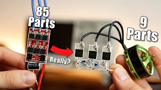
PWM controllers use a manual potentiometer. But what if you want to control it using an Arduino or similar? Could you use the Arduino to control a small logic level MOSFET, which would feed into a simple circuit with a capacitor and a resistor? If you solder the terminals for this in where the manual potentiometer was connected, the pulse length would determine the voltage between the terminals, and thus affect the PWM controller as if you were using the manual potentiometer.
Date: 2020-09-05
Related videos


Comments and reviews: 9
INFINITY
Hello, I really liked your video sir!
Sir, actually I need your help!
sir, I am working on a project where I have to use a suitable potentiometer that can oppose 2 Amperes of D. C current!
I have 6 A of D. C current and I want to use 4 A of D. C current by stopping 2 Amperes using a potentiometer or anyhow possible!
6-2 = 4 ( 4 Amperes I want to achieve.
Can you please tell me which potentiometer should I use or how can I do that anyway?
reply
Sigmas
I am working on a laptop fan. I could really use some help. My laptop fans are running at full speed. It is a motherboard issue but replacing the motherboard could cost me over 500 USD. The laptop is ASUS ROG Strix GL702ZC. I bought some pin adapters so that I don't have to destroy the fans to splice the wires. I connected a 10K ohm potentiometer. I may need some assistance.
reply
Tick
thanks for the video, i have a hard drive box that works well but after some hours i am going crazy with the sound of the fan, and i did not want to put a big set of parts in the box to slow the fan but maybe just use a 10k POT maybe 2k Pot but dont want the pot to get hot
reply
thanks for the video, i have a hard drive box that works well but after some hours i am going crazy with the sound of the fan, and i did not want to put a big set of parts in the box to slow the fan but maybe just use a 10k POT maybe 2k Pot but dont want the pot to get hot
reply
Sankar
can you make a video on a project that is included, NodeMCU + Relay module + Robotdyn AC light dimmer + Blynk? or can I have the coding? I'm trying to make a project like that but really poor in coding. Will you please help?
reply
can you make a video on a project that is included, NodeMCU + Relay module + Robotdyn AC light dimmer + Blynk? or can I have the coding? I'm trying to make a project like that but really poor in coding. Will you please help?
reply
Tristun
It's really hard to find cheap 220 ohm potentiometers for some reason, I see 10K ohm and higher though everywhere. Would a 10K ohm resistor work well with a very small voltage? Like 1. 5 volts from a AA battery?
reply
It's really hard to find cheap 220 ohm potentiometers for some reason, I see 10K ohm and higher though everywhere. Would a 10K ohm resistor work well with a very small voltage? Like 1. 5 volts from a AA battery?
reply
LowSpecChaos
sooo. wait i could spice into my CPUS pwm wire alone. plug the fans red & blacks into a molex, but then reconnect pwm wire to my fans? therefor allowing me to control all fans via CPU fan header 1
reply
sooo. wait i could spice into my CPUS pwm wire alone. plug the fans red & blacks into a molex, but then reconnect pwm wire to my fans? therefor allowing me to control all fans via CPU fan header 1
reply
ward
i'm searching for a solution the change my 'voltage in' of a my dummy load. the 'voltage in' is 54. 8 V. max load is 4 X 50 W (a little more with ventilation, display, etc. Any suggestions? Kind regards.
reply
i'm searching for a solution the change my 'voltage in' of a my dummy load. the 'voltage in' is 54. 8 V. max load is 4 X 50 W (a little more with ventilation, display, etc. Any suggestions? Kind regards.
reply
mohamed
Thank you for the explanation. I built the circuit but found not much difference with a variable resister. So I scrambled the circuit. Guess I have to build it again. Tq
reply
Thank you for the explanation. I built the circuit but found not much difference with a variable resister. So I scrambled the circuit. Guess I have to build it again. Tq
reply
AleLoons
Your video are definitely more instructive than my electronic lessons at school. Thank you a lot.
You made me want restart with electronic; )
reply
Your video are definitely more instructive than my electronic lessons at school. Thank you a lot.
You made me want restart with electronic; )
reply
Add a review, comment
Other channel videos