Why This Circuit Works When It Shouldn’t
video description
Date: 2026-01-23
Related videos



Comments and reviews: 20
Kagamiinchan
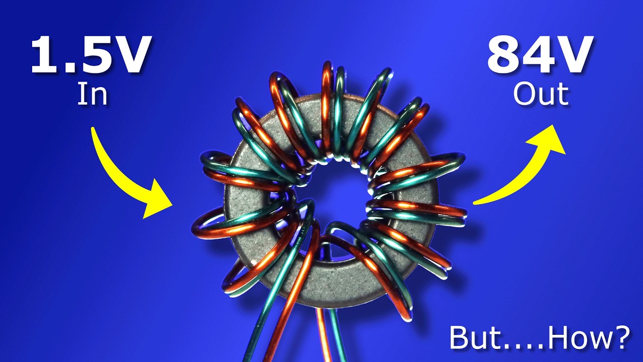
Nice video, loved the detailed explanations of the physics behind the circuit. I learned about joule thiefs years ago, they're certainly very simple and fascinating energy harvesting circuits; but nowadays I wonder about how efficient they really are when compared to buck-boost circuits and charge pumps, which when properly designed tend to have very high conversion efficiencies, frequently over 95%.
It seems to me like part of the energy ends up being wasted as the toroid's magnetic field grows, since the current flowing through it is directed to ground through the transistor until the secondary reaches zero volts and the current flows through the LED. Is that correct And if so, how much energy is actually being wasted during this phase of the circuit's operation
reply
Nice video, loved the detailed explanations of the physics behind the circuit. I learned about joule thiefs years ago, they're certainly very simple and fascinating energy harvesting circuits; but nowadays I wonder about how efficient they really are when compared to buck-boost circuits and charge pumps, which when properly designed tend to have very high conversion efficiencies, frequently over 95%.
It seems to me like part of the energy ends up being wasted as the toroid's magnetic field grows, since the current flowing through it is directed to ground through the transistor until the secondary reaches zero volts and the current flows through the LED. Is that correct And if so, how much energy is actually being wasted during this phase of the circuit's operation
reply
shanegibby
Great vid. Explained VERY well. Thank you. (Also wondering why you have chosen to explain it with Conventional Theory instead of Electron. neg to pos)
From AI:
Theories of electrical flow center on two main concepts: Conventional Theory, which assumes current flows from positive ) to negative (-) terminals (historical, used in power systems) and Electron Theory, which reflects the actual movement of negatively charged electrons from negative (-) to positive ) (used in electronics. Despite the opposite directions, both models yield the same results for circuit analysis, with conventional flow being easier for many, while electron flow is physically accurate.
reply
Great vid. Explained VERY well. Thank you. (Also wondering why you have chosen to explain it with Conventional Theory instead of Electron. neg to pos)
From AI:
Theories of electrical flow center on two main concepts: Conventional Theory, which assumes current flows from positive ) to negative (-) terminals (historical, used in power systems) and Electron Theory, which reflects the actual movement of negatively charged electrons from negative (-) to positive ) (used in electronics. Despite the opposite directions, both models yield the same results for circuit analysis, with conventional flow being easier for many, while electron flow is physically accurate.
reply
GodbornNoven
yes, in principle a jewel thief works like a transformer, which can increase the voltage by decreasing the current.
even in a dead cell, it can still store energy, just that the voltage it can provide isnt higher than the forward voltage of the led. The power provided actually decreases a little because of losses but the led still lights up because the reason it wasn't lighting up in the first place wasn't a lack of power, it was a lack of voltage.
plus the pulsating nature of the jewel thief is also a nice boost to efficiency, since our eyes can't really perceive a different between continuous light and a quickly pulsating light.
reply
yes, in principle a jewel thief works like a transformer, which can increase the voltage by decreasing the current.
even in a dead cell, it can still store energy, just that the voltage it can provide isnt higher than the forward voltage of the led. The power provided actually decreases a little because of losses but the led still lights up because the reason it wasn't lighting up in the first place wasn't a lack of power, it was a lack of voltage.
plus the pulsating nature of the jewel thief is also a nice boost to efficiency, since our eyes can't really perceive a different between continuous light and a quickly pulsating light.
reply
MrCuddlyable
The video designer does a fair simulation of a 1940s school teacher lecturing about inductance who never heard of a transistor, combined with a description of a transistor that applies only to an NPN junction transistor without mentioning NPN junction or showing its standard circuit symbol, combined with a LED where its P- and N- materials are sketched but not explained. Transistors that look like the one (dramatically burned) in the video might be PNP, FET, MOSFET, Unijunction or Point-contact and not work at all here.
reply
The video designer does a fair simulation of a 1940s school teacher lecturing about inductance who never heard of a transistor, combined with a description of a transistor that applies only to an NPN junction transistor without mentioning NPN junction or showing its standard circuit symbol, combined with a LED where its P- and N- materials are sketched but not explained. Transistors that look like the one (dramatically burned) in the video might be PNP, FET, MOSFET, Unijunction or Point-contact and not work at all here.
reply
charlescz1974
Interesting that these basic electronics proofs, simple math, and circuitry, was typical High School education back in the 1960’s and 70’s. My kids, college grads never heard of ohms law: E=I/R or the AC version, or impedance, reactance, inductance or virtually any basic electronics. Very strange. Let alone what a transistor really is. I started thinking it was layered technology; being that there was no longer a need to go to the component or IC level because it’s a world of replaceable not reparable.
reply
Interesting that these basic electronics proofs, simple math, and circuitry, was typical High School education back in the 1960’s and 70’s. My kids, college grads never heard of ohms law: E=I/R or the AC version, or impedance, reactance, inductance or virtually any basic electronics. Very strange. Let alone what a transistor really is. I started thinking it was layered technology; being that there was no longer a need to go to the component or IC level because it’s a world of replaceable not reparable.
reply
Geopholus
1st off modern light emitting diodes require so little current, secondly, voltage multipliers using square waves thru coils to create a differential voltage spike are over 130 years old (Yeah I guess more. try ignition coil on Your old car. 3rdly this is just electronics 101, nothing remotely new, novel or surprising, actually the one to one transformer fired forward and backward on alternate cycles of the oscillator would double the voltage even if the oscillator was a sine oscillator. wow
reply
1st off modern light emitting diodes require so little current, secondly, voltage multipliers using square waves thru coils to create a differential voltage spike are over 130 years old (Yeah I guess more. try ignition coil on Your old car. 3rdly this is just electronics 101, nothing remotely new, novel or surprising, actually the one to one transformer fired forward and backward on alternate cycles of the oscillator would double the voltage even if the oscillator was a sine oscillator. wow
reply
Skrylex_
Exactly what i had in mind, when i first heard, make not working battery make lot of powa
Now keep in mind, i am not educated in electronics nor physics, i hardly know anything in those regions, but i am still interested in learning such things.
So basically whats going on if i understood correctly, this circuit transfers stable electricity into short pulses, just like a capacitor, like a marx generator, if i got anything wrong, please apologize, i already said, i am not educated
reply
Exactly what i had in mind, when i first heard, make not working battery make lot of powa
Now keep in mind, i am not educated in electronics nor physics, i hardly know anything in those regions, but i am still interested in learning such things.
So basically whats going on if i understood correctly, this circuit transfers stable electricity into short pulses, just like a capacitor, like a marx generator, if i got anything wrong, please apologize, i already said, i am not educated
reply
engineering_mindset
The principles behind the Joule Thief circuit can be a little involved. Assuming your audience has no prior knowledge can make your presentation a little wordy. It might be better to reference other videos and explain the principles there. Also the term conventional current is a misnomer since it has not been the convention in over a century. Engineering Current or better yet Electron-hole Current would be a better term. Other than those points, well done.
reply
The principles behind the Joule Thief circuit can be a little involved. Assuming your audience has no prior knowledge can make your presentation a little wordy. It might be better to reference other videos and explain the principles there. Also the term conventional current is a misnomer since it has not been the convention in over a century. Engineering Current or better yet Electron-hole Current would be a better term. Other than those points, well done.
reply
fuzzy-pillar
A little detail that was glossed over is that transitors base voltage determines what the effective voltage is on the collector. By applying a negative voltage to the base, you're setting that value to a negative number, which means that it will actually have more blocking power than if it were just kept at 0. This only really matters when dealing with high-efficiency designs, but it makes a HUGE difference if the collector can ever go negative.
reply
A little detail that was glossed over is that transitors base voltage determines what the effective voltage is on the collector. By applying a negative voltage to the base, you're setting that value to a negative number, which means that it will actually have more blocking power than if it were just kept at 0. This only really matters when dealing with high-efficiency designs, but it makes a HUGE difference if the collector can ever go negative.
reply
cogwheel42
Apparently the forward voltage of an LED is not based on the materials but actually represents the energy lost by an electron when it emits a photon of the given wavelength. A forward voltage of 1. 6 means an electron loses 1. 6 electron-volts of energy, which corresponds to red light. This also means that normal diodes, with their 0. 7-ish forward voltage would function as IR leds.
reply
Apparently the forward voltage of an LED is not based on the materials but actually represents the energy lost by an electron when it emits a photon of the given wavelength. A forward voltage of 1. 6 means an electron loses 1. 6 electron-volts of energy, which corresponds to red light. This also means that normal diodes, with their 0. 7-ish forward voltage would function as IR leds.
reply
Nono-hk3is
Great animations.
I'd still like someone to analyze the impact of the number of turns in the coil: more turns means more resistance, but is there a benefit that comes with that cost Stronger magnetic field, but what does that translate into. Higher efficiency maybe
I'd also love to see someone experiment with different numbers of turns in the primary vs secondary windings.
reply
Great animations.
I'd still like someone to analyze the impact of the number of turns in the coil: more turns means more resistance, but is there a benefit that comes with that cost Stronger magnetic field, but what does that translate into. Higher efficiency maybe
I'd also love to see someone experiment with different numbers of turns in the primary vs secondary windings.
reply
OrphanedPaper
and there is no noticed magnetic flux in a dc current its thought because of alignment of electron & positrons(nuclides aliment or compensation inducing the electron shift) if you want to see electron and positron use a, AA or AAA battery and a compass switching the negative and positive ends of the battery pointed towards the north or south end of the compass needle
reply
and there is no noticed magnetic flux in a dc current its thought because of alignment of electron & positrons(nuclides aliment or compensation inducing the electron shift) if you want to see electron and positron use a, AA or AAA battery and a compass switching the negative and positive ends of the battery pointed towards the north or south end of the compass needle
reply
jeffmccrea9347
I hate to be the picky one in the room but electrons, (the subatomic particles responsible for electricity, are negatively charged. in the early part of your illustration, you show electron flow emanating from the positive terminal of a cell to the negative terminal. DC currant ALWAYS flows from negative to positive. Just sayin'.
reply
I hate to be the picky one in the room but electrons, (the subatomic particles responsible for electricity, are negatively charged. in the early part of your illustration, you show electron flow emanating from the positive terminal of a cell to the negative terminal. DC currant ALWAYS flows from negative to positive. Just sayin'.
reply
dannyglover7681
I'm still a bit confused as to how this works in terms of the whole energy cannot be created nor destroyed rule. We're starting with low energy (dead battery) then playing tug of war with magnetic fields to push more electrons harder (freaking faraday batman that's sick) but how does this create energy as in increased voltage
reply
I'm still a bit confused as to how this works in terms of the whole energy cannot be created nor destroyed rule. We're starting with low energy (dead battery) then playing tug of war with magnetic fields to push more electrons harder (freaking faraday batman that's sick) but how does this create energy as in increased voltage
reply
satibel
5: 12 correction: almost immediately, in the transistor's datasheet there's a fall time rating, e. g. for a 2n2222 it should turn off in less than 60ns, which doesn't sound like much, but if you're working with 100khz, that's gonna make your waveform look more like a sine wave than a square wave, because there's also a rise time.
reply
5: 12 correction: almost immediately, in the transistor's datasheet there's a fall time rating, e. g. for a 2n2222 it should turn off in less than 60ns, which doesn't sound like much, but if you're working with 100khz, that's gonna make your waveform look more like a sine wave than a square wave, because there's also a rise time.
reply
sFeral
put a capacitor and diode (LED) in series with it between the B and C ends of the coils, with cathode of the diode placed on the B, and then place another LED across the capacitor. This way energy is accumulated in the capacitor and you can get pretty high voltages, to light up a small neon bulb for ex.
reply
put a capacitor and diode (LED) in series with it between the B and C ends of the coils, with cathode of the diode placed on the B, and then place another LED across the capacitor. This way energy is accumulated in the capacitor and you can get pretty high voltages, to light up a small neon bulb for ex.
reply
engineering_mindset
I think i have seen your other video yesterday - the one with once blinking led and PC adapter upcycling: ) now i know what you wanted to achieve: D
5: 20 - it only fixes fr an NPN transistor and in the case of a PNP one some more changes in the circuit would be needed ofc.
reply
I think i have seen your other video yesterday - the one with once blinking led and PC adapter upcycling: ) now i know what you wanted to achieve: D
5: 20 - it only fixes fr an NPN transistor and in the case of a PNP one some more changes in the circuit would be needed ofc.
reply
KaliFissure
You're using the hysteresis lag in the iron and the reaction time of the transistor to create a feedback oscillator. Nice!
Fundamental physical< qualities are overlooked nowadays when there is a chip for everything.
I have a video on the simplest oscillator.
reply
You're using the hysteresis lag in the iron and the reaction time of the transistor to create a feedback oscillator. Nice!
Fundamental physical< qualities are overlooked nowadays when there is a chip for everything.
I have a video on the simplest oscillator.
reply
MarshallLapenta
Question
What if the circuit has a voltage spike
What size or thickness was the copper wire used for the coil
Does the switch ever get stuck into position
What if we make the Toroid core thicker or bigger, would the magnetic field be bigger as well
reply
Question
What if the circuit has a voltage spike
What size or thickness was the copper wire used for the coil
Does the switch ever get stuck into position
What if we make the Toroid core thicker or bigger, would the magnetic field be bigger as well
reply
arydant
Very common circuit called a flyback converter. It is used in nearly every power supply today. This is the simplest circuit for demonstration. The LED is a type of diode but it's normally a rectifier diode but in this application does the same thing and lights up.
reply
Very common circuit called a flyback converter. It is used in nearly every power supply today. This is the simplest circuit for demonstration. The LED is a type of diode but it's normally a rectifier diode but in this application does the same thing and lights up.
reply
Add a review, comment
Other channel videos