DIY Wireless Energy Transfer System
video description
Date: 2020-09-05
Related videos


Comments and reviews: 9
Andy
Abundance of information which is very interesting. Is there a simple IC ready made board out there which you can show as alternative instead of building the circuit ourselves? The schematics and and the build are excellent but just saying for non technical people like me which likes electronics, would actually loves a simpler way to show how wireless charging works.
reply
BlossomSwirly
Hi My wireless Fantasy Charger is blinking Red Blue and wont charge the phone. im using a universal wireless charger. After a few hrs the Base got hot and it started blinking. please help. looking to tear down the circuit and modify it or repair it but its all micro circuit and ICs help please.
reply
Ab
Every transformer is a wireless energy transfer, whether with an iron core or an air core. Bifilar wound wires (2 wires twisted together, as John Bedini taught, is also wireless energy transfer. Each of these designs does not have a direct connected wire between these side A and side B.
reply
Every transformer is a wireless energy transfer, whether with an iron core or an air core. Bifilar wound wires (2 wires twisted together, as John Bedini taught, is also wireless energy transfer. Each of these designs does not have a direct connected wire between these side A and side B.
reply
Varun
hey great scott, i am doing a project on wireless charging of ev batteries. how can i modify this circuit to charge a the lithium battery you made for the ebike. it will help me very much if you could offer some advice on the same.
reply
hey great scott, i am doing a project on wireless charging of ev batteries. how can i modify this circuit to charge a the lithium battery you made for the ebike. it will help me very much if you could offer some advice on the same.
reply
Mf
Hai,
I saw your circuit, i have a doubt
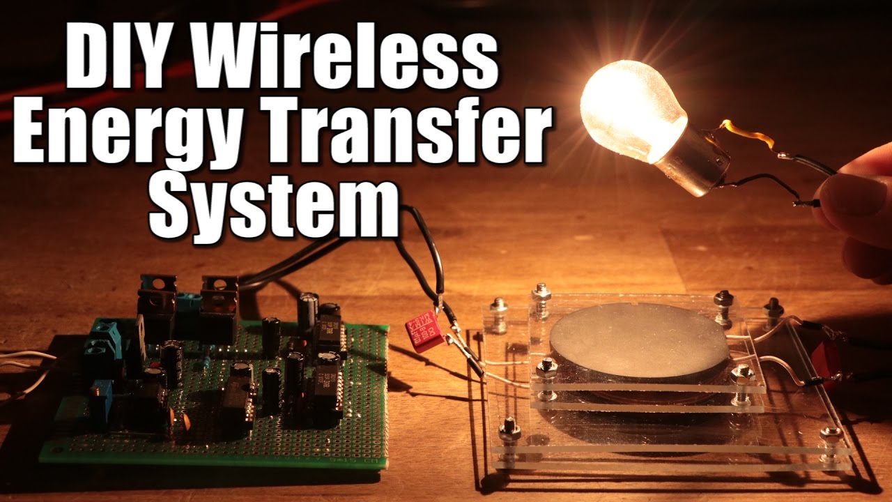
In your video at 5: 13 you connected 10k resistor the upper side mosfet's gate and source but in your easyEDA schematic you connected that resistor to gate and drain!
Which is true?
reply
Hai,
I saw your circuit, i have a doubt
In your video at 5: 13 you connected 10k resistor the upper side mosfet's gate and source but in your easyEDA schematic you connected that resistor to gate and drain!
Which is true?
reply
prabhat
A small error in the schematic, there has to be a pull down resistor between gate and source, rather than a pull up resistor in between gate and drain as in the schematic for high side switching mosfets
reply
A small error in the schematic, there has to be a pull down resistor between gate and source, rather than a pull up resistor in between gate and drain as in the schematic for high side switching mosfets
reply
Bo
GreatScott! Do you have any recommended reference material (e. g. textbooks, articles, etc) that you use to prepare for these or do you solely rely on the datasheets for the various chips you are using?
reply
GreatScott! Do you have any recommended reference material (e. g. textbooks, articles, etc) that you use to prepare for these or do you solely rely on the datasheets for the various chips you are using?
reply
prabhat
I tried to make the h bridge with the same parts except for the inverter I used 74hc14, but then I don't get any output at the gates of mosfet drivers! Can anyone please help
reply
I tried to make the h bridge with the same parts except for the inverter I used 74hc14, but then I don't get any output at the gates of mosfet drivers! Can anyone please help
reply
Ritvik
Hey! I am working on a similar project. I am trying so hard but get stuck somewhere or the else. Can we please please connect for further details?
reply
Hey! I am working on a similar project. I am trying so hard but get stuck somewhere or the else. Can we please please connect for further details?
reply
Add a review, comment
Other channel videos