Should you use Liquid Metal for everything? A Raspberry Pi gives the answer!
video description
In many situations though, at least one of the surfaces is also concave (or convex) on a similar or larger order of magntiduce compared to the roughness. You then have not only the roughness 'gaps' to fill, but also the additional gap from these non-flat surfaces. And with that the thickness of the applied paste layer and viscosity of it, compared to the mounting pressure and mounting pressure distribution. This often results in a layer of paste between the surfaces with a thickness larger than the typical size of surface roughness features. It is here where liquid metal can really help out a lot. Being a much more homogenous substance (i. e. no particles of certain size which dominate the thermal performance, it works much better with these 'larger' gaps. It also commonly results in a thinner interface layer because of the generally lower viscosity compared to paste.
Generally, the rougher, the less flat, and/or the lower mounting pressure, the better liquid metal works (compartively, that is.
Date: 2022-03-14
Related videos


Comments and reviews: 9
Ken
Super flatten and mirror polish the contact surface of your heatsink and it should stick to an equally polished and flat CPU glass or metal surface. Surface tension bonds the two surfaces HARD. NO thermal compound can fit. NO thermal compound can help, it would only harm. Just remember: a thin heatsink thermal transfer area mass like you find in a laptop will expand, contract and warp due to the unequal convection of heat away from the block. When this warping occurs: loss of surface tension and loss of heat transfer occur. A new set of Japanese knife sharpening stones up to 30, 000 grit followed by jeweler's rouge (going black, brown, red, green to white) on leather then canvas, finishing on deerskin then bare canvas will polish to a mirror finish. If top of cpu is not mirror shiny flat Take it off and MAKE it flat and shiny. Then reflow or re-socket it onto board. I start by drawing surface across a mill file until low spots become as shiny as the previously high spots. Then go to higher and higher grit stones without jumping large grit steps. Final results are better and quicker thermal conductivity that NO thermal compound could EVER deliver.
reply
uRiBiTo666
Liquid metal is best used for enthusiasts wanting to get the most out of their system. In my case I have an older 6th gen i7 and a relatively large heatsink. I delided the CPU and replaced the internal thermal paste with liquid metal. I saw a 20 degree drop, and I'm running 4. 5GHz with temps in the mid 70s. The Heatsink itself does have regular thermal paste since it does have aluminum, like your Raspberry Pi heatsink.
I also tried it on my laptop and saw no difference. The CPU reaches 100 degrees fairly quickly and maxes out at 40w after about 10 seconds of load. The heatsink is just too small so after it heats up it becomes the limiting factor.
Also worth noting, liquid metal will damage copper in the long term. The less dangerous application is on nickel-plated copper, since the liquid metal doesn't really diffuse into nickel much. However it will slowly diffuse into copper, which can be seen as the metal drying up. It means that it will require periodic re-applications and once you use liquid metal your heatsink will no longer perform well on thermal paste.
reply
Majromax
(Edit: This comment is wrong, see reply)
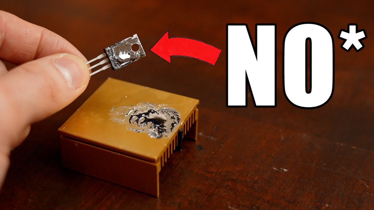
Unfortunately, the transistor test at the end had an incorrect methodology.
By construction, the transistor was always generating about 16W of heat. At steady state, that heat must flow to the heat sink, which must in turn exchange that heat with the ambient environment. The temperature of the heat sink is limited by its thermal contact with the atmosphere, evidently about 2. 5K/W in your test environment.
That means that the heat sink will have a steady-state temperature of 60C regardless of the contact between transistor and heat sink. You could replace the liquid metal with no interface at all and see the same sort of steady state.
To measure the system properly, you need to look at the temperature of the transistor itself, perhaps with a thermocouple attached to the non-heat-sink side. The Raspberry Pi test setup was superior here because it reported on-die temperatures.
reply
(Edit: This comment is wrong, see reply)
Unfortunately, the transistor test at the end had an incorrect methodology.
By construction, the transistor was always generating about 16W of heat. At steady state, that heat must flow to the heat sink, which must in turn exchange that heat with the ambient environment. The temperature of the heat sink is limited by its thermal contact with the atmosphere, evidently about 2. 5K/W in your test environment.
That means that the heat sink will have a steady-state temperature of 60C regardless of the contact between transistor and heat sink. You could replace the liquid metal with no interface at all and see the same sort of steady state.
To measure the system properly, you need to look at the temperature of the transistor itself, perhaps with a thermocouple attached to the non-heat-sink side. The Raspberry Pi test setup was superior here because it reported on-die temperatures.
reply
Klave
You should really show the whole thermal circuit from the silicon to the heatsink and the air, it may be that the large area and the thin layer produces a small thermal resistance in comparison to the other thermal resistances.
Maybe a better application would be for a 3d printer heat block, temperature sensor and hot end. Errors in the temperature are far more critical and temperatures are much higher, above 200C at least. Also the thermal paste becomes dry and hard, how well it conducts then is a question no one deals with. Unfortunately the thermal transfer block is made of aluminium but some people have switched to copper. That electrical conductivity is also a problem with high power power supplies.
I wonder if it will be effective if you use a copper shim or tape to protect the aluminium heatsink, the added layers would probably make it worse thermally.
Very interesting video and lots of hard work, thanks you.
reply
Ryan
Hey! On delidding-- you might have more success (and some additional ideas for videos) if you use a thermal camera. It excels at showing to you the slight differences / average temp of that lid, so you know exactly when it is getting close to solder melt temp, and where you might need to focus heat to keep things even.
On thermal cameras: I want to DIY breed a thermal camera, with a laser distance scanner, with a PTZ camera-type base. to automatically monitor for people and animals in my (heavily wooded) backyard, without cameras/visible lights nor laser beam detectors. It's true that even dual laser beam detectors are often triggered by falling leaves. Dont ask how I know: ( It would be cool to have something I can centrally locate like that as well-- instead of needing to have many devices at all the corners of the perimeter. (Or several cameras)
I am very surprised there is not such a device on the market yet
reply
Walter
This actually answers some things I've been wondering about overclocking a Raspberry Pi, though i was aware of the limits of cryonaut's liquid metal cooling.
With regards to the upper limit on Raspberry pi's overclocking speed, I believe ARM processor's have a built in limit to the caching system on the chip.
To exceed that speed you'd need to find a way to bypass L1 cache speed limit, which may not be possible without going all the way back to the chip manufacturer. There may be a software tool that allows you to alter the operating speed, but it would involve flashing the cache read/write instructions, which is a bit deeper than making the processor go faster.
reply
John
When most people think of liquid metal they think of mercury which is toxic. This is gallium, and gallium reacts badly to aluminium because it diffuses between the grain boundaries of the microcrystals of aluminium and breaks down their bonding which exposed to air turns the aluminium into aluminium oxide and remains a catalyst. This is why it is banned from aviation. A small amount placed on structural aluminium will cause it to disintegrate rapidly, and the gallium dissipates across the surface. There are videos showing how it can destroy a scooter or bike frame, as well as padlocks.
reply
BF3
That stuff welded my cpu to my heatsink to the point that it pulled the cpu out of the socket while the socket was locked. I then had to use a screwdriver to pry the chip free. Google it. Don't give me any karp on how to install it either. I have been building and overclocking since I took my pentium 100, built a custom water loop, and took it to 166. I also take apart and reshape air coolers (including the main pad) so they will fit the custom configuration I have designed.
reply
GreatScott!
For this video I have to say a few words. I was not the best in thermodynamics in university. So there is a possibility that some technical terms are incorrect. But I repeated the shown tests/experiments a few times and always ended up with the same results. I also did lots of research on this topic and I really hope my final conclusion is correct. But as always, feel free to state your own opinion in the comment section. But please, no insults. Thanks: -)
reply
Add a review, comment
Other channel videos


 12:47
12:47