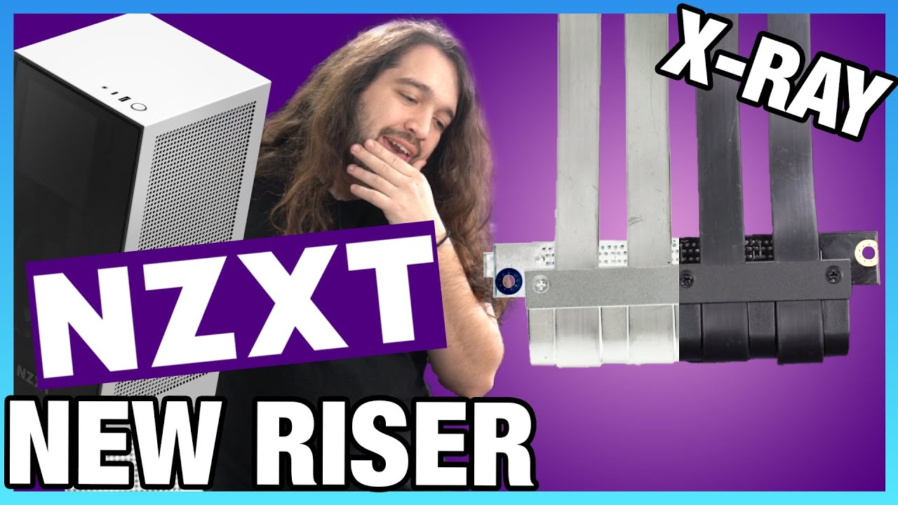
Fire or No Fire: New NZXT H1 Riser X-Ray & Testing (NZXT H1 PCIe Riser Fix)
video description
Date: 2021-03-10
Related videos


Comments and reviews: 9
movax20h
The extra vias around the mounting holes are plated, and the primary purpose of them is to add extra mechanical support and the current to flow between a screw face and the copper plane, which could be on the same or other, or inner layers. Also these vias will ensure connection, even if the plated main hole is damaged. They are not strictly needed, but are quite common these days.
Also whetever the mounting hole should be connected to ground of the circuit, is debatable. Sometimes they should, sometimes they shouldn't. In this case, beceuase it can be carrying quite a big amount of current, it actually shouldn't be used for grounding. For example, if the ground wires in the raiser, or the other side of the riser ground pins become damaged, the current will flow, but now via the mounting point and chasis, instead using intended route using the cable. This is problematic, because sometimes a resetable or electronic fuses could be on motherboard to monitor the return current, and if the current instead goes via the chasis, weird things could happen. It also makes signal integrity worse. The return path should be parallel and close to the input path, for various complex reasons. The other issue with using mounting hole to also be connected to chasis ground, is now you have issues with screw torque and/or the mating force between the screw, PCB, and the threads in chasis, and coatings of the screw and chasis, which all add to variability and unknowns in your resistance and reliability. Using mounting holes for grounding is perfectly valid strategy in some situations and actually needed, but in many other cases actually should or must be avoided.
I think the mounting holes should be plated and with vias, just like they are here, for mechanical strength, but should not be connected to the ground on the PCIe slot, as this might mess things up.
reply
The extra vias around the mounting holes are plated, and the primary purpose of them is to add extra mechanical support and the current to flow between a screw face and the copper plane, which could be on the same or other, or inner layers. Also these vias will ensure connection, even if the plated main hole is damaged. They are not strictly needed, but are quite common these days.
Also whetever the mounting hole should be connected to ground of the circuit, is debatable. Sometimes they should, sometimes they shouldn't. In this case, beceuase it can be carrying quite a big amount of current, it actually shouldn't be used for grounding. For example, if the ground wires in the raiser, or the other side of the riser ground pins become damaged, the current will flow, but now via the mounting point and chasis, instead using intended route using the cable. This is problematic, because sometimes a resetable or electronic fuses could be on motherboard to monitor the return current, and if the current instead goes via the chasis, weird things could happen. It also makes signal integrity worse. The return path should be parallel and close to the input path, for various complex reasons. The other issue with using mounting hole to also be connected to chasis ground, is now you have issues with screw torque and/or the mating force between the screw, PCB, and the threads in chasis, and coatings of the screw and chasis, which all add to variability and unknowns in your resistance and reliability. Using mounting holes for grounding is perfectly valid strategy in some situations and actually needed, but in many other cases actually should or must be avoided.
I think the mounting holes should be plated and with vias, just like they are here, for mechanical strength, but should not be connected to the ground on the PCIe slot, as this might mess things up.
reply
auwdioslave
As stated by earlier comments, the tubes around the large mounting holes are vias in the PCB. These are small holes which are drilled through the PCB before the plating process. Just as the large screw hole, they get plated with copper during electroplating.
Plated mounting holes are often used to create an electrical connection between the ground potential of a circuit and the housing in which it is mounted. This is done to improve safety and can reduce the electromagnetic interference around the board. Adding vias through the pad surrounding a plated mounting hole is done to ensure a proper connection, even if the plating in the actual mounting hole is damaged by the screw.
reply
As stated by earlier comments, the tubes around the large mounting holes are vias in the PCB. These are small holes which are drilled through the PCB before the plating process. Just as the large screw hole, they get plated with copper during electroplating.
Plated mounting holes are often used to create an electrical connection between the ground potential of a circuit and the housing in which it is mounted. This is done to improve safety and can reduce the electromagnetic interference around the board. Adding vias through the pad surrounding a plated mounting hole is done to ensure a proper connection, even if the plating in the actual mounting hole is damaged by the screw.
reply
filippo
Electrical engineeer with pcb design experience here...
The tubes that run the length of the board (called vias in jargon) are used to add more mechanical strenght to the joint (since they are copper plated) the pcb material will creep over time (basically squish and deform permanently) under the screw pressure, making the board thinner and thus the screw will not hold down the board correctly.
They are very important in high vibration environment (think automotive) since the board vibrating due to the loose screw can be damaged.
In a PC case, they are always a good practice, but probably not strictly necessaty (there won't be much vibration)
reply
Electrical engineeer with pcb design experience here...
The tubes that run the length of the board (called vias in jargon) are used to add more mechanical strenght to the joint (since they are copper plated) the pcb material will creep over time (basically squish and deform permanently) under the screw pressure, making the board thinner and thus the screw will not hold down the board correctly.
They are very important in high vibration environment (think automotive) since the board vibrating due to the loose screw can be damaged.
In a PC case, they are always a good practice, but probably not strictly necessaty (there won't be much vibration)
reply
nikomo
The tubes are plated vias - a hole is drilled through, after which copper is added via a deposition process, and then more copper is added to that base via an electroplating process.
In this case, it has been done to provide low impedance to the case. The screw will have the best contact on the top of the board, but the ground plane seems to be on the bottom. These vias provide the shortest possible path from the screw to the ground plane. The solder dimples are simply formed by opening up the solder mask, so the solder paste squeegee applies paste at those locations. Surface tension takes care of forming the shape.
reply
The tubes are plated vias - a hole is drilled through, after which copper is added via a deposition process, and then more copper is added to that base via an electroplating process.
In this case, it has been done to provide low impedance to the case. The screw will have the best contact on the top of the board, but the ground plane seems to be on the bottom. These vias provide the shortest possible path from the screw to the ground plane. The solder dimples are simply formed by opening up the solder mask, so the solder paste squeegee applies paste at those locations. Surface tension takes care of forming the shape.
reply
DaKermitFrog
Calling all computer nerds: Black screen after installing AMD radeons drivers for r9 270x. Gets to about the login screen and stays black - uninstall the drivers = no black screen.
About to install that card into a newer ryzen system and test installing windows 10 since idk what to do.
How do I test if my gpu died? D sub still outputting graphics signal from the gpu to monitor, but drivers won't work with it. 1.0 score on windows index and games won't launch.
reply
Calling all computer nerds: Black screen after installing AMD radeons drivers for r9 270x. Gets to about the login screen and stays black - uninstall the drivers = no black screen.
About to install that card into a newer ryzen system and test installing windows 10 since idk what to do.
How do I test if my gpu died? D sub still outputting graphics signal from the gpu to monitor, but drivers won't work with it. 1.0 score on windows index and games won't launch.
reply
catbertz
Nice coverage! Great to see a quality replacement part. I'm open to the idea that NZXT initially got screwed with a bad third party sourced board, but everything after that is on them. As soon as problems and fires popped up, they needed to jump fast and transparently. Lack of communication and coverups are always worse than the original problem.
reply
Nice coverage! Great to see a quality replacement part. I'm open to the idea that NZXT initially got screwed with a bad third party sourced board, but everything after that is on them. As soon as problems and fires popped up, they needed to jump fast and transparently. Lack of communication and coverups are always worse than the original problem.
reply
itech
The fact that the riser was a generic third-party unit and not made by NZXT explains a lot - they added a new screw hole and that ended up going through a 12V plane. Still a massive cock-up but you can see how it happened. I think the problem is that case manufacturers don't really know about PCB design because they outsource it all.
reply
The fact that the riser was a generic third-party unit and not made by NZXT explains a lot - they added a new screw hole and that ended up going through a 12V plane. Still a massive cock-up but you can see how it happened. I think the problem is that case manufacturers don't really know about PCB design because they outsource it all.
reply
Sebastian
Even though I don't have an nzxt case neither do any of my friends but I still really appreciate you took so much intiative and efforts and resolved this public hazard which could have been deadly
Great job Steve
Edit - I wish I had some money to follow you on patreon or biy some merch but still
reply
Even though I don't have an nzxt case neither do any of my friends but I still really appreciate you took so much intiative and efforts and resolved this public hazard which could have been deadly
Great job Steve
Edit - I wish I had some money to follow you on patreon or biy some merch but still
reply
Michael
08:41 - that is a fiducial on the corner, used for machine vision to define coordinates on the PCB for accurate positioning of features from drills to silk screens to keep outs etc.. The tubes are vias and are just there to help keep the ground planes at the same potential across the length of the board.
reply
08:41 - that is a fiducial on the corner, used for machine vision to define coordinates on the PCB for accurate positioning of features from drills to silk screens to keep outs etc.. The tubes are vias and are just there to help keep the ground planes at the same potential across the length of the board.
reply
Add a review, comment
Other channel videos