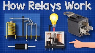
How Relays Work - Basic working principle electronics engineering electrician amp
video description
Date: 2023-11-17
Related videos





Comments and reviews: 30
Hopelessand
Nice lesson. Now that electromechanical relays are being rapidly replaced by solid state devices, it is interesting to look back on the ways they were designed and used in the sixty years since I began, and subsequently retired from, working aircraft electronics. For one thing, many relays are available with multiple sets of contacts, for instance 6PDT. Numbers of such relays can be wired to perform complex logic functions by wiring the primary circuit of each relay, along with remote inputs from switches and sensors, through secondary contacts in other relays. For instance, relay A coil will operate only when relay B is off (use common and NC contact of relay B, and relay C is on (use com and NO contact of relay C. In fact, simple digital computers have been built using only relays for logic processing.
Many power relays, or contactors, will have sets of auxiliary contacts that switch as the main contacts move. The main contacts in a contactor are frequently in 3 sets for switching 3-phase power. The primary circuit for any given contactor may be wired through auxiliary contacts of multiple contactors to ensure that one and only one power source is connected to a bus or load at any given time.
You might mention that latching relays are not always necessary for effecting a latching, or holding, circuit. Any relay can be configured as a holding relay by wiring the active wire to the coil in parallel with a set of the same relay's contacts so that once the active primary wire operates the relay, the parallel circuit through its contacts will maintain the coil circuit even after the input signal goes away. Various methods of resetting, or deactivating, the relay are used, such as a NC push-to-open switch in the parallel circuit. When a contractor needs to be under positive control to open or close only when a discrete signal is received, latching relays are used. I have seen contactors for aircraft generator power evolve from from common relay operation that requires continuous power in coil circuit, to mechanically-latched contactors with separate coils for open and closed function, to magnetically latched contactors with two coils, one to close and one to open, to magnetically latched contactors with a single coil that is closed by a momentary current of one polarity, and opened by a momentary current thought the same coil but of the opposite polarity. It was fun.
reply
Nice lesson. Now that electromechanical relays are being rapidly replaced by solid state devices, it is interesting to look back on the ways they were designed and used in the sixty years since I began, and subsequently retired from, working aircraft electronics. For one thing, many relays are available with multiple sets of contacts, for instance 6PDT. Numbers of such relays can be wired to perform complex logic functions by wiring the primary circuit of each relay, along with remote inputs from switches and sensors, through secondary contacts in other relays. For instance, relay A coil will operate only when relay B is off (use common and NC contact of relay B, and relay C is on (use com and NO contact of relay C. In fact, simple digital computers have been built using only relays for logic processing.
Many power relays, or contactors, will have sets of auxiliary contacts that switch as the main contacts move. The main contacts in a contactor are frequently in 3 sets for switching 3-phase power. The primary circuit for any given contactor may be wired through auxiliary contacts of multiple contactors to ensure that one and only one power source is connected to a bus or load at any given time.
You might mention that latching relays are not always necessary for effecting a latching, or holding, circuit. Any relay can be configured as a holding relay by wiring the active wire to the coil in parallel with a set of the same relay's contacts so that once the active primary wire operates the relay, the parallel circuit through its contacts will maintain the coil circuit even after the input signal goes away. Various methods of resetting, or deactivating, the relay are used, such as a NC push-to-open switch in the parallel circuit. When a contractor needs to be under positive control to open or close only when a discrete signal is received, latching relays are used. I have seen contactors for aircraft generator power evolve from from common relay operation that requires continuous power in coil circuit, to mechanically-latched contactors with separate coils for open and closed function, to magnetically latched contactors with two coils, one to close and one to open, to magnetically latched contactors with a single coil that is closed by a momentary current of one polarity, and opened by a momentary current thought the same coil but of the opposite polarity. It was fun.
reply
Anthony
Hey there, I have a question on an HVAC system component.
To keep things simple we have a single speed outdoor unit with a 24v circuit that goes to a contactor relay.
Y- wire is the 24v hot wire
C- is your common wire.
In this scenario we had pressure switches high and low (HPCO & LPCO) in series of the C circuit.
We want to install a 24v Time Delay on Make (TDM) in the circuit.
The question is. Would the TDM work on the C side, or do we need to install it in the Y side.
Also, if we need to install it in the Y side do we also need to swap over the PCOs to break the Hotwire before the TDM?
going back and forth with a buddy of mine and my dad.
I think we need to switch everything over to the Y hot wire side and they dont think it makes a difference.
Although they think it is best practice to put these type of switches on the hot wire side. The argument still stands. Does it make a difference or not?
reply
Hey there, I have a question on an HVAC system component.
To keep things simple we have a single speed outdoor unit with a 24v circuit that goes to a contactor relay.
Y- wire is the 24v hot wire
C- is your common wire.
In this scenario we had pressure switches high and low (HPCO & LPCO) in series of the C circuit.
We want to install a 24v Time Delay on Make (TDM) in the circuit.
The question is. Would the TDM work on the C side, or do we need to install it in the Y side.
Also, if we need to install it in the Y side do we also need to swap over the PCOs to break the Hotwire before the TDM?
going back and forth with a buddy of mine and my dad.
I think we need to switch everything over to the Y hot wire side and they dont think it makes a difference.
Although they think it is best practice to put these type of switches on the hot wire side. The argument still stands. Does it make a difference or not?
reply
nick
I really wish you would change the explanation of the latching circuit. it is not how most relays work. typically the latching function is done with a set of normally open contacts, on the relay itself, wired in parallel with the monetary electrical component that starts the relay function. They have a normally closed stop button in series with that parallel circuit to shut this latched circuit off. I really like your stuff and use your videos in industrial electronics classes I teach in a Community College. This part of this one will confuse the hell out of students though and I am reluctant to use this one.
reply
I really wish you would change the explanation of the latching circuit. it is not how most relays work. typically the latching function is done with a set of normally open contacts, on the relay itself, wired in parallel with the monetary electrical component that starts the relay function. They have a normally closed stop button in series with that parallel circuit to shut this latched circuit off. I really like your stuff and use your videos in industrial electronics classes I teach in a Community College. This part of this one will confuse the hell out of students though and I am reluctant to use this one.
reply
macknumber9
I am troubleshooting a refridgerator that the compressor will not kick on.
I have narrowed it down to the relay that is on the circuit board (not the one that plugs into the compressor.
Im not sure exactly how to test it. i tested for 12 volts and i have 12 volts dc but on the other post next to it i only get 6 volts. no idea if i even need to test that side or not. im not getting any voltage coming out of the relay thats supposed to go to the compressor (120 volts ac) so either the relay has failed or something has failed prior to the relay
reply
I am troubleshooting a refridgerator that the compressor will not kick on.
I have narrowed it down to the relay that is on the circuit board (not the one that plugs into the compressor.
Im not sure exactly how to test it. i tested for 12 volts and i have 12 volts dc but on the other post next to it i only get 6 volts. no idea if i even need to test that side or not. im not getting any voltage coming out of the relay thats supposed to go to the compressor (120 volts ac) so either the relay has failed or something has failed prior to the relay
reply
education
How come current is not flowing through the flywheel diode when the circuit is not interrupted and just operating normally? How come it is only flowing through the flywheel diode when energy is dissipating from the electromagnetic field? I understand that electricity always takes the path of least resistance back to the source but how does it bypass the flywheel diode and the wiring in parallel when the circuit is closed and electricity is flowing through the whole thing?
reply
How come current is not flowing through the flywheel diode when the circuit is not interrupted and just operating normally? How come it is only flowing through the flywheel diode when energy is dissipating from the electromagnetic field? I understand that electricity always takes the path of least resistance back to the source but how does it bypass the flywheel diode and the wiring in parallel when the circuit is closed and electricity is flowing through the whole thing?
reply
HeyMorganHere
I bought a 12-position knob switch to control several circuts of LEDs (mostly in pairs. My hope was to have Position 1 as OFF, Position 2 illuminate Pair A, Position 3 illuminate Pair B, Position 4 illuminate both A&B, etc. (The project is a model house and garden; I wanted to be able to turn lights on/off in groups to look more realistic. The concept is simple but the wiring is complicated for a beginner, and I've bitten off far more than I can chew.
reply
I bought a 12-position knob switch to control several circuts of LEDs (mostly in pairs. My hope was to have Position 1 as OFF, Position 2 illuminate Pair A, Position 3 illuminate Pair B, Position 4 illuminate both A&B, etc. (The project is a model house and garden; I wanted to be able to turn lights on/off in groups to look more realistic. The concept is simple but the wiring is complicated for a beginner, and I've bitten off far more than I can chew.
reply
Blooter
Hi Nice video. I have a boat (RIB) with an inboard diesel engine and z drive. The trim and tilt function which lifts the drive unit and propellor up and down is controlled from the helm using a up down rocker switch. The circuit contains a hydraulic pump which in turn is operated by two 24v relays, ( one for up and the other for down) I think they are the normally off type. Im wondering if solid state relays would be a better and more reliable alternative?
reply
Hi Nice video. I have a boat (RIB) with an inboard diesel engine and z drive. The trim and tilt function which lifts the drive unit and propellor up and down is controlled from the helm using a up down rocker switch. The circuit contains a hydraulic pump which in turn is operated by two 24v relays, ( one for up and the other for down) I think they are the normally off type. Im wondering if solid state relays would be a better and more reliable alternative?
reply
Dragoco
hi i want to, im on this project, its like vaccum door using for clinical lab, it has 2 door 2 light ( red and green ) 2 EM Lock and 2 pair of door sensor, the logic is like this, if i go through 1 door, another door will lock and red will light up ( detect using door sensor ), if the both door closed, it will turned green. and not lock. can u explained the connection to me? because im bit confused. the EM Lock, lights and door sensor control by relay
reply
hi i want to, im on this project, its like vaccum door using for clinical lab, it has 2 door 2 light ( red and green ) 2 EM Lock and 2 pair of door sensor, the logic is like this, if i go through 1 door, another door will lock and red will light up ( detect using door sensor ), if the both door closed, it will turned green. and not lock. can u explained the connection to me? because im bit confused. the EM Lock, lights and door sensor control by relay
reply
Raid
Im well acquainted with mechanical relays, from small 24VDC ones all the way up to big 460VAC 8 pole relays, but I stayed till the end for the flywheel diode explanation because the nerds on stack exchange were either extremely rude and belittling (as per usual with that toxic website) or they over-explained with lengthy lectures with a bunch of laws, theory, and formulas.
You managed to answer that question in under 30 seconds. You are a legend
reply
Im well acquainted with mechanical relays, from small 24VDC ones all the way up to big 460VAC 8 pole relays, but I stayed till the end for the flywheel diode explanation because the nerds on stack exchange were either extremely rude and belittling (as per usual with that toxic website) or they over-explained with lengthy lectures with a bunch of laws, theory, and formulas.
You managed to answer that question in under 30 seconds. You are a legend
reply
Christian
I work in hvac and I was dealing with an ice cube relay that went bad for the condenser fan motor. Low voltage powered the relays high voltage terminals except for the one where a wire from the condenser fan motor went to. I checked the terminal right under it #4 I believe and it was showing 120 to ground. Then I just swapped the leg to that terminal. Motor came back on. I just wanted to understand it more thoroughly then what I already do.
reply
I work in hvac and I was dealing with an ice cube relay that went bad for the condenser fan motor. Low voltage powered the relays high voltage terminals except for the one where a wire from the condenser fan motor went to. I checked the terminal right under it #4 I believe and it was showing 120 to ground. Then I just swapped the leg to that terminal. Motor came back on. I just wanted to understand it more thoroughly then what I already do.
reply
mdpmd11
7: 43 Im currently in the process of fixing my Toaster oven. I troubleshot the failure to a circuit board. Then my instructor at school helped me isolate the broken relay that controlled the upper heating element. My instructor also recommended to replace the other two identical relays on the circuit board, as PM.
Ill be fixing my toaster oven, and performing PM on it for less than $3!
reply
7: 43 Im currently in the process of fixing my Toaster oven. I troubleshot the failure to a circuit board. Then my instructor at school helped me isolate the broken relay that controlled the upper heating element. My instructor also recommended to replace the other two identical relays on the circuit board, as PM.
Ill be fixing my toaster oven, and performing PM on it for less than $3!
reply
Colban
Will make a small automation through my solar inverter's dry contact signal.
When on battery mode, it switches to NC status and will send a signal to a contactor with 1 NO and 1 NC position. Once the contactor energizes a red strobe will activate, indicating the unit is running in battery mode and when de energized a steady green light will be on through the NC position.
reply
Will make a small automation through my solar inverter's dry contact signal.
When on battery mode, it switches to NC status and will send a signal to a contactor with 1 NO and 1 NC position. Once the contactor energizes a red strobe will activate, indicating the unit is running in battery mode and when de energized a steady green light will be on through the NC position.
reply
Sam
Ok I'm pretty new to electronics and mechanics. So in a car horn, theres a relay I'm pretty sure. Now I think the horn circuit is attached to the 87 pin, and when the relay is in the 87a state, nothing happens. Would it be possible to swap the the horn to the 87a state, so its always on until some presses the horn. This is purely hypothetical so ethics don't apply
reply
Ok I'm pretty new to electronics and mechanics. So in a car horn, theres a relay I'm pretty sure. Now I think the horn circuit is attached to the 87 pin, and when the relay is in the 87a state, nothing happens. Would it be possible to swap the the horn to the 87a state, so its always on until some presses the horn. This is purely hypothetical so ethics don't apply
reply
xEvilNeverDiesx
I hate being dumb. I just can't process this information even though it's great information. I was always an A+ student during high school and college. But my mind just can't comprehend electrics. It's so annoying since I understand most things. But electrical things literally blow my mind, and I just can't understand what I am being told.
reply
I hate being dumb. I just can't process this information even though it's great information. I was always an A+ student during high school and college. But my mind just can't comprehend electrics. It's so annoying since I understand most things. But electrical things literally blow my mind, and I just can't understand what I am being told.
reply
john
Hello, given the typical Bosch Style (or Amp/Tyco) 12VDC automotive relay; with an average of 80 ohms for the primary coil winding (12VDC, 80 ohm = 150mA,
approximately how many turns of wire in the primary coil winding?
also, what gauge (or mm2) wire is typically used?
reply
Hello, given the typical Bosch Style (or Amp/Tyco) 12VDC automotive relay; with an average of 80 ohms for the primary coil winding (12VDC, 80 ohm = 150mA,
approximately how many turns of wire in the primary coil winding?
also, what gauge (or mm2) wire is typically used?
reply
Dan
Great video.
We studied relays during my college course and this video helped as a refresher. As for where I've seen relays used, I've seen them used in elevator controllers, fire alarm panels (latching the signal, HVAC equipment and traffic signal controllers to name a few.
reply
Great video.
We studied relays during my college course and this video helped as a refresher. As for where I've seen relays used, I've seen them used in elevator controllers, fire alarm panels (latching the signal, HVAC equipment and traffic signal controllers to name a few.
reply
Chieu
we have relays on some of the avionics system for the kc 135 which I used to work on when I was in the military. We rarely see them besides the click sound they would make when we pull the circuit breaker for certain systems.
reply
we have relays on some of the avionics system for the kc 135 which I used to work on when I was in the military. We rarely see them besides the click sound they would make when we pull the circuit breaker for certain systems.
reply
SD
I wonder, if electrons has to complete the circuit! Then when we connect live with neutral or positive n negative directly without any device, why does it short-circuit? Or there's a huge spark? Isn't that completes the circuit?
reply
I wonder, if electrons has to complete the circuit! Then when we connect live with neutral or positive n negative directly without any device, why does it short-circuit? Or there's a huge spark? Isn't that completes the circuit?
reply
Chucky
I am working on a useless machine (turn itself off when turned on) and I think a relay will be useful. I am using sensors to detect temp and vibration after which the circuit will turn off with the help of relay and Arduino
reply
I am working on a useless machine (turn itself off when turned on) and I think a relay will be useful. I am using sensors to detect temp and vibration after which the circuit will turn off with the help of relay and Arduino
reply
Shahida
Respectfully, at 6: 10, you say that n- type has lots of electrons. That gives us a notion of n-type being electron rich and p-type as electron deficit. But ain't the two types electrically neutral?
Thank you.
reply
Respectfully, at 6: 10, you say that n- type has lots of electrons. That gives us a notion of n-type being electron rich and p-type as electron deficit. But ain't the two types electrically neutral?
Thank you.
reply
Bibilia
Thank you for the in depth functions of a relay. Am looking to use it for AC/ DC switch functions between solar generator & AC power grid connection to provide UPS. Your thoughts and recommendations are welcome.
reply
Thank you for the in depth functions of a relay. Am looking to use it for AC/ DC switch functions between solar generator & AC power grid connection to provide UPS. Your thoughts and recommendations are welcome.
reply
VideomasterPDB
I love electronics. I have a masters degree in electronic and electrical engineering. However I was never taught any of this. I'm now in my job which uses relays and using this video to get me through
reply
I love electronics. I have a masters degree in electronic and electrical engineering. However I was never taught any of this. I'm now in my job which uses relays and using this video to get me through
reply
randomator666
I know this is 2 years late but I've recently been subcontracted to service these mechanical relays at a power station and they have hundreds of these operating all the time to keep everything going
reply
I know this is 2 years late but I've recently been subcontracted to service these mechanical relays at a power station and they have hundreds of these operating all the time to keep everything going
reply
Cyrus
Once I come back this deployment, Ill pay you. You are literally helping me a lot things that I didnt know before. Truly appreciate it.
reply
Once I come back this deployment, Ill pay you. You are literally helping me a lot things that I didnt know before. Truly appreciate it.
reply
Ethan
Whats's stopping an arc from happening between the two contacts? Or when they get close they just weld themselves together?
reply
Whats's stopping an arc from happening between the two contacts? Or when they get close they just weld themselves together?
reply
Boerikoe
Excellent video, thank you very much for sharing and helping others to recognize possible solutions for their projects.
reply
Excellent video, thank you very much for sharing and helping others to recognize possible solutions for their projects.
reply
Lucretius
This was fascinating Ty! Someone tried to explain this using paper and a pencil. I said no thanks Ill watch a video!
reply
This was fascinating Ty! Someone tried to explain this using paper and a pencil. I said no thanks Ill watch a video!
reply
Angel
This was so incredibly helpful. I'm in school for automotive tech and the first class is electrical. Thank you so much.
reply
This was so incredibly helpful. I'm in school for automotive tech and the first class is electrical. Thank you so much.
reply
Adeyemi
I work in oil and gas offshore facility, I've seen different types of relay ranging from AC, DC 24vdc, 48vdc, 240vac
reply
I work in oil and gas offshore facility, I've seen different types of relay ranging from AC, DC 24vdc, 48vdc, 240vac
reply
Spenzr
At first, i was like this is just a switch with an extra step. After watching this video, i love relays
reply
At first, i was like this is just a switch with an extra step. After watching this video, i love relays
reply
Add a review, comment
Other channel videos