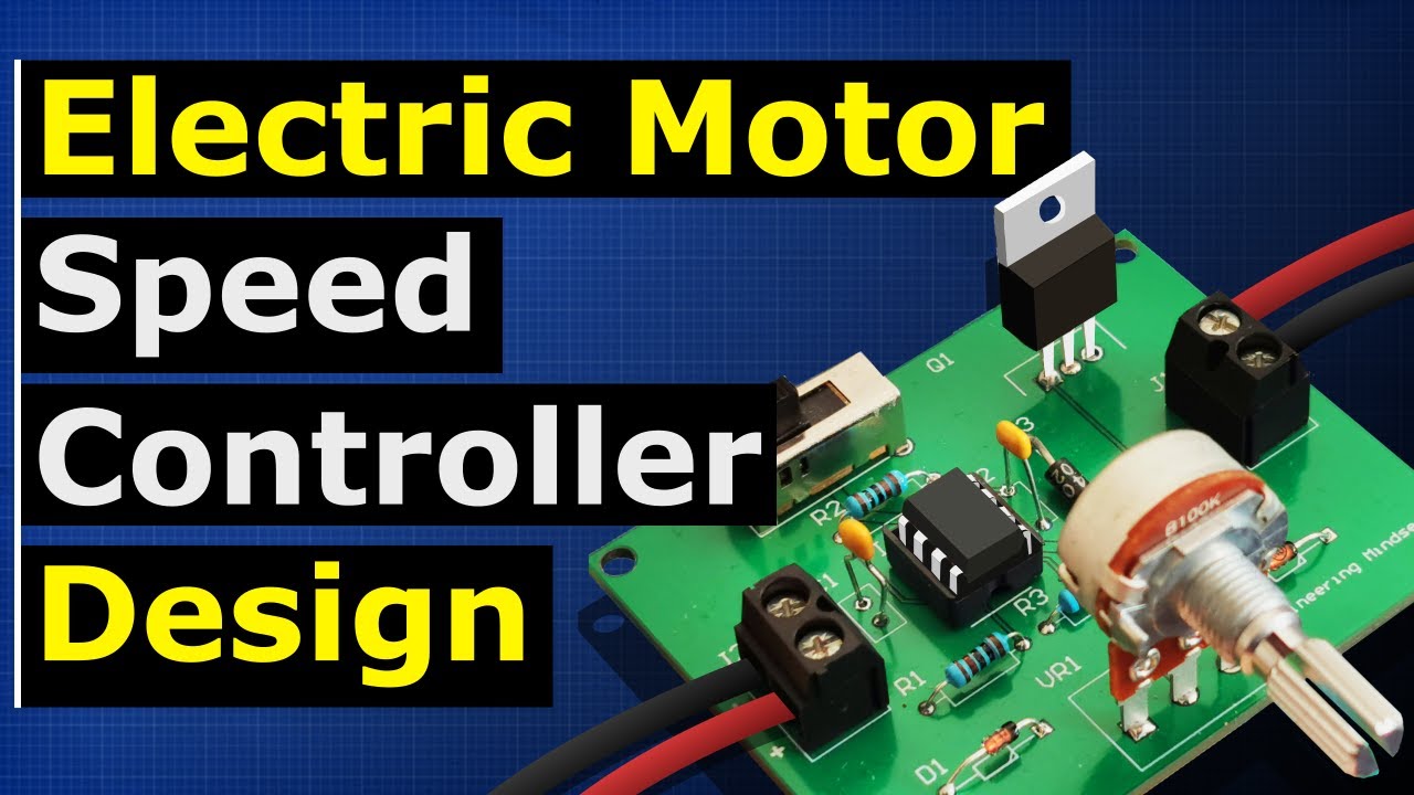
Motor speed controller tutorial - PWM how to build
video description
Date: 2023-11-17
Related videos






Comments and reviews: 30
Tiger
Outstanding class. I did keep re-running several parts of the video, and putting the speed down to 0. 75x to get a hang of it. And now I know how a 555 timer works. Thanks for this.
For a backstory, I am new to electronics and have a good inclination towards repairing my stuff.
When I went to learn from a master, the first thing he asked me was do you know how a 555 timer works.
I told him no. He sent me away, telling me that he will take me in once I figure out what makes a 555 timer a 555 timer. At least the basics. And then he will take me in. He was like its the heart of concepts of everything electronics.
So much more to learn, but this is a really good place. I already subbed to a course on Udemy, but this has done a better job at giving me an understanding.
If you read this far, thanks for being patient with my rant, and I hope you have a great day ahead. :)
reply
Outstanding class. I did keep re-running several parts of the video, and putting the speed down to 0. 75x to get a hang of it. And now I know how a 555 timer works. Thanks for this.
For a backstory, I am new to electronics and have a good inclination towards repairing my stuff.
When I went to learn from a master, the first thing he asked me was do you know how a 555 timer works.
I told him no. He sent me away, telling me that he will take me in once I figure out what makes a 555 timer a 555 timer. At least the basics. And then he will take me in. He was like its the heart of concepts of everything electronics.
So much more to learn, but this is a really good place. I already subbed to a course on Udemy, but this has done a better job at giving me an understanding.
If you read this far, thanks for being patient with my rant, and I hope you have a great day ahead. :)
reply
Vincent
May I suggest replacing the 1N4007 diode with a 1N5819 Schottky barrier diode? (40 V, 1 A, same size package) That eliminates the current tail caused by the standard recovery diode, taking a lot of transition stress of the diode and MOSFET. It also has a somewhat lower voltage drop, which will increase the efficiency of the circuit. That would also allow a 1 nF timing capacitor, increasing switching speed up to 14, 280 Hz, which puts the motor into continuous conduction. The high frequency switching noise will be inaudible. (cut the gate drive resistor between pin 3 of the 555 timer and the gate pin of the MOSFET down to 47 Ohms)
All this can be done with no modifications what so ever, to the PC boards you just had made!
reply
May I suggest replacing the 1N4007 diode with a 1N5819 Schottky barrier diode? (40 V, 1 A, same size package) That eliminates the current tail caused by the standard recovery diode, taking a lot of transition stress of the diode and MOSFET. It also has a somewhat lower voltage drop, which will increase the efficiency of the circuit. That would also allow a 1 nF timing capacitor, increasing switching speed up to 14, 280 Hz, which puts the motor into continuous conduction. The high frequency switching noise will be inaudible. (cut the gate drive resistor between pin 3 of the 555 timer and the gate pin of the MOSFET down to 47 Ohms)
All this can be done with no modifications what so ever, to the PC boards you just had made!
reply
Giuliano
Awesome but unfortunately I am too new to circuitry to understand everything; yet design something of this nature. But maybe you can help me with a couple questions; first I have a electric motor 36v250w; it has 3 cables; I was experimenting with it and figured out the current has to alternate for the motor to move forward; for example the brown wich I suspect is ground; is connected to - of battery. Then when I alternatively touch the other two on the + the motor moves forward; what is happening here? Second; is there a way to run this motor or do you know what kind speed controller needs to used or Alternatively; could you create this? Thanks for any help.
reply
Awesome but unfortunately I am too new to circuitry to understand everything; yet design something of this nature. But maybe you can help me with a couple questions; first I have a electric motor 36v250w; it has 3 cables; I was experimenting with it and figured out the current has to alternate for the motor to move forward; for example the brown wich I suspect is ground; is connected to - of battery. Then when I alternatively touch the other two on the + the motor moves forward; what is happening here? Second; is there a way to run this motor or do you know what kind speed controller needs to used or Alternatively; could you create this? Thanks for any help.
reply
BUTCH
i want to control 12 volt dc motor or higher voltage! with a 0 to 5 volts and use this pwm modual ibt-2. can i do it with a hall effect potentiometer with a 0 to 5 volts dc output? i have been doing some reading but i am just not getting it! i am sure this will work i need some one to tell me that it will work! plus the capacitors in the circuit gives a ramp effect when energized! so if i had a poteniometer to increase decrease i would get a faster responce! am i correct or not? i need to know this! thanks
reply
i want to control 12 volt dc motor or higher voltage! with a 0 to 5 volts and use this pwm modual ibt-2. can i do it with a hall effect potentiometer with a 0 to 5 volts dc output? i have been doing some reading but i am just not getting it! i am sure this will work i need some one to tell me that it will work! plus the capacitors in the circuit gives a ramp effect when energized! so if i had a poteniometer to increase decrease i would get a faster responce! am i correct or not? i need to know this! thanks
reply
SANCHEZ305
man thayt was intense. i wrote all of it down pausing it as u went along and i must say i learned alot here i am gonna build mine from scratch seeing how im just starting up and i gotta find a motor and all that so im statring all this just to power a huge stereo im trying to build from scratch this is a great journey and i love every min of it learning all i can thanks again.
reply
man thayt was intense. i wrote all of it down pausing it as u went along and i must say i learned alot here i am gonna build mine from scratch seeing how im just starting up and i gotta find a motor and all that so im statring all this just to power a huge stereo im trying to build from scratch this is a great journey and i love every min of it learning all i can thanks again.
reply
Roman
I built this exact design, and am using the exact components listed.
For some reason, the motor runs slowly, and the potentiometer has no effect. In fact, I can disconnect the gate on the MOSFET complete, and it still runs, at 1. 5 volts. I cant seem to figure out why current is flowing through the MOSFET even though I have nothing connected at the gate. Im dumbfounded.
reply
I built this exact design, and am using the exact components listed.
For some reason, the motor runs slowly, and the potentiometer has no effect. In fact, I can disconnect the gate on the MOSFET complete, and it still runs, at 1. 5 volts. I cant seem to figure out why current is flowing through the MOSFET even though I have nothing connected at the gate. Im dumbfounded.
reply
education
Is there a way of setting a minimum duty cycle with this circuit?
For example if the electric motor doesn't like to run below 40% duty cycle can you make the circuit supply a 0% output until the input signal gets it to over 40%.
reply
Is there a way of setting a minimum duty cycle with this circuit?
For example if the electric motor doesn't like to run below 40% duty cycle can you make the circuit supply a 0% output until the input signal gets it to over 40%.
reply
Bobby
The wiper of the potentiometer in this video is on pin 3. I thought the wiper was pin 2. Forgive me. I'm a novice trying to teach myself so I'm attempting to recreate this using Kicad, and don't want to wire things incorrectly
reply
The wiper of the potentiometer in this video is on pin 3. I thought the wiper was pin 2. Forgive me. I'm a novice trying to teach myself so I'm attempting to recreate this using Kicad, and don't want to wire things incorrectly
reply
Abhishek
Shouldn't the discharge line connection be below the discharge diode. As in the current connection, the discharge line connected above the discharge diode will draw current even from the battery through the resistor R1.
reply
Shouldn't the discharge line connection be below the discharge diode. As in the current connection, the discharge line connected above the discharge diode will draw current even from the battery through the resistor R1.
reply
The
Does the AVG voltage drop with frequency or is it the time on to time off ratio? The AVG is the integration over time so the area of a fifty percent duty cycle is still the same no matter what frequency?
reply
Does the AVG voltage drop with frequency or is it the time on to time off ratio? The AVG is the integration over time so the area of a fifty percent duty cycle is still the same no matter what frequency?
reply
Steve
Your bread board is so clean. I'm going to start working to keep my work as tidy. I like how all your grounds are on one side and all your hots are on the other, makes it very easy to follow.
reply
Your bread board is so clean. I'm going to start working to keep my work as tidy. I like how all your grounds are on one side and all your hots are on the other, makes it very easy to follow.
reply
Abraham
hello, I know this was a year ago but why not just connect the resistor to gat to ground first then connect from the gate to the 555? Would that make a difference? thank you for all you do.
reply
hello, I know this was a year ago but why not just connect the resistor to gat to ground first then connect from the gate to the 555? Would that make a difference? thank you for all you do.
reply
Бидон
10: 53 look are the potentiometer area. Are you sure that th output of discharching diode should be connected to the output of charging resistor? I think it will only waste power.
reply
10: 53 look are the potentiometer area. Are you sure that th output of discharching diode should be connected to the output of charging resistor? I think it will only waste power.
reply
Joe's
why do your diodes look so much bigger than mine? I got the exact same parts numbers 1N4148 and 1N4007 but mine look like dwarfs compared to the ones I see on your circuit
reply
why do your diodes look so much bigger than mine? I got the exact same parts numbers 1N4148 and 1N4007 but mine look like dwarfs compared to the ones I see on your circuit
reply
Sunny
Thank you for sharing. i have finished all your electronics basic, and watch this video at 0. 75 speed, but i still still no idea whats going on after the 15 mins
reply
Thank you for sharing. i have finished all your electronics basic, and watch this video at 0. 75 speed, but i still still no idea whats going on after the 15 mins
reply
OrionPrime
Ok that's great now I have to use 500w motor 24 volt what to modify to make this same circuit to work for the required motor i mentioned with hall sensor?
reply
Ok that's great now I have to use 500w motor 24 volt what to modify to make this same circuit to work for the required motor i mentioned with hall sensor?
reply
Gabriel
Wondering if can I use this circuit to power a small e-bike with a 24 volt, 10 amp (250 watt) brushed DC motor by changing the mosfet to an IRFP260NPBF?
reply
Wondering if can I use this circuit to power a small e-bike with a 24 volt, 10 amp (250 watt) brushed DC motor by changing the mosfet to an IRFP260NPBF?
reply
Exciton
Excellent video, how do know all these things about building a circuits? Is there a good book which explains building complicated circuit projects?
reply
Excellent video, how do know all these things about building a circuits? Is there a good book which explains building complicated circuit projects?
reply
Fanta
Never before seen better explanation of 555 ic, how it works. Very nice from you mate even nothing new for me but I know it will help many.
reply
Never before seen better explanation of 555 ic, how it works. Very nice from you mate even nothing new for me but I know it will help many.
reply
Luis
I understood a lot of what you explained, you made it so simple to understand, thank you very much for this tutorial I appreciate it
reply
I understood a lot of what you explained, you made it so simple to understand, thank you very much for this tutorial I appreciate it
reply
Tayyab
I have watched only 5 min of your video and I am subscribing such a good way of describing and in detail. Thanx and appreciate it.
reply
I have watched only 5 min of your video and I am subscribing such a good way of describing and in detail. Thanx and appreciate it.
reply
TUCW
14: 45 It is recommended to place the screw terminals closer to the MOSFET and have the traces exposed so more current can flow.
reply
14: 45 It is recommended to place the screw terminals closer to the MOSFET and have the traces exposed so more current can flow.
reply
RAT7163
How does the capacitor discharge? Is it because transistor provides a path of lower resistance away from the potentiometer?
reply
How does the capacitor discharge? Is it because transistor provides a path of lower resistance away from the potentiometer?
reply
MD
How many ampere load output can be taken? I will run the dc motor load. The circuit can be run by making the speed low and high.
reply
How many ampere load output can be taken? I will run the dc motor load. The circuit can be run by making the speed low and high.
reply
It's
Uhm, is it ok if potentiometer, led, wire and battery is used? Will it be work the same as this? Please i need your answer
reply
Uhm, is it ok if potentiometer, led, wire and battery is used? Will it be work the same as this? Please i need your answer
reply
Higgypig
Is there a way to scale this up with a 20v power source? I'm building one of these for use with a 20v dewalt battery.
reply
Is there a way to scale this up with a 20v power source? I'm building one of these for use with a 20v dewalt battery.
reply
Solar
I want to build a 25 amp pwm but I want to know if I can ad a higher wattage mosfet for the amp with your circuit
reply
I want to build a 25 amp pwm but I want to know if I can ad a higher wattage mosfet for the amp with your circuit
reply
Tony
This has got to be the best description of the internal workings of the 555 ic I have ever seen. Many thanks.
reply
This has got to be the best description of the internal workings of the 555 ic I have ever seen. Many thanks.
reply
Graham
Brilliant, better than any book, presents in visual and audio form which helps me learn a lot. Thank you.
reply
Brilliant, better than any book, presents in visual and audio form which helps me learn a lot. Thank you.
reply
Tim
This is rated five wow's. Perfect explanation of the 555 TIMER AND CIRCUIT. Awesome video. Great teacher.
reply
This is rated five wow's. Perfect explanation of the 555 TIMER AND CIRCUIT. Awesome video. Great teacher.
reply
Add a review, comment
Other channel videos